Originally named CBUS by co-founder Gil Fuchs, CBUS is an 'open' protocol for Model Railway use. The protocol and other useful information is hosted on the MERG public website (see further support links). CBUS is not owned or controlled by MERG but the co-founders Gil Fuchs and Mike Bolton are active members. MERG members are able to purchase a range of CBUS kits.
As support for CBUS continues to evolve, these help pages are not a definitive CBUS network guide and contain considerable simplification of the CBUS scheme. They are aimed at helping new users to JMRI or CBUS, not systems developers who should consult the full protocol specification and Developer's Guide hosted by MERG.
For details of how to setup a connection to a CBUS network, you should refer to the JMRI help pages, or other documentation, for your chosen manufacturer's hardware.
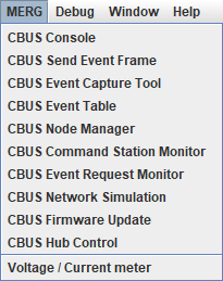
CBUS tools are accessed from the menu for your chosen system connection.The example shows a connection to MERG hardware. The available tools may vary with the system connection
CBUS events are transmitted as a one-to-many network. Connected modules receive all network messages and choose whether or not to act on them. This enables multiple modules to act on a single event, eg:
CBUS events generally come in two types: "ON" and "OFF".
Events can be short (SLiM) events, eg +11 for event 11 on.
Events can be long (FLiM) events, eg -N2E7 for node 2 event 7 off.
JMRI, being both a consumer and producer of events, can send and receive on any node number and any event.
CBUS events are stored as
These are accessed via JMRI Tables, ie PanelPro > Tools > Tables > ( Sensors, Turnouts or Lights ) .
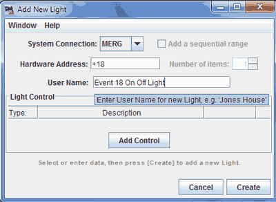
When the table loads, click on " Add... " button at bottom left to create an item.
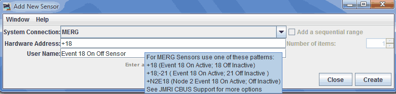
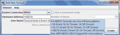
For most short events, you just need to enter the number. Here are a few examples :
| Hardware Address | Meaning | Event Consumed as Sensor |
Event Produced as Turnout |
Event Produced as Light turned |
|---|---|---|---|---|
+18
|
Event 18 On Event 18 Off |
Sets sensor Active Sets sensor Inactive |
Thrown Closed |
On Off |
+18;+21
|
Event 18 On Event 21 On |
Sets sensor Active Sets sensor Inactive |
Thrown Closed |
On Off |
+18;-21
|
Event 18 On Event 21 Off |
Sets sensor Active Sets sensor Inactive |
Thrown Closed |
On Off |
+N2E18
|
Node 2 Event 18 On Node 2 Event 18 Off |
Sets sensor Active Sets sensor Inactive |
Thrown Closed |
On Off |
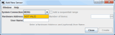
You will need to enter the Hardware Address in a JMRI recognised format to create the
event.
If the create button is grayed out, check your hardware naming format.
Adding a User Name (using any characters) when creating a table item may make accessing it easier in JMRI.
Remember to save your tables!
For more on events, see JMRI system naming with CBUS.
DCC is not a requirement for CBUS or JMRI. Many DC layouts use CBUS + JMRI for route setting, signalling and track occupancy purposes.
For full details of using CBUS in a DCC system you should refer to the JMRI help pages, or other documentation, for your chosen manufacturer's hardware. Some brief details are included below.
JMRI will send and receive CBUS encoded DCC packets over the CBUS network. These and can be monitored with the CBUS console
Loco sessions are best viewed with the CBUS Command Station Monitor, which displays the sessions in a table format.
All of the programs within the JMRI suite (including the JMRI WiThrottle server) internally share the same command station slot for a given loco address, so all of JMRI appears to the command station as a single throttle for any single address.
JMRI (via the CBUS Node Manager) can tell if a command station is available which supports the CBUS steal or share features, when throttles are requested which are already in use by something external to JMRI (i.e. a CBUS connected throttle).
When a JMRI application requests a loco (which is already in a CBUS session), JMRI will check the main Throttles Preferences.
If Silent Steal or Silent Share has been selected, this will be the default action.
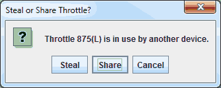
If neither have been checked and you are using the main JMRI Throttle, you will be asked if you want to Steal, Share, or cancel.
If you are using an automation script and neither option is checked, the system will attempt to acquire a Share on the session.
When WiThrottle encounters an existing non-JMRI Throttle session and is asked Share / Steal / Cancel?, the main JMRI Throttle silent Steal / silent Share options are checked for preferred behaviour.
If neither option is checked, the WiThrottle client may be asked if it wants to steal the session, the sharing question is unsupported.
The command station may disable or enable steal / share at any point, so even if you have a preferred option, an automation script may attempt to use the non-preferred option to obtain the session.
When a Throttle session has been stolen / cancelled from outside of JMRI, any open JMRI throttle window for that loco will cease to accept commands, ie throttle slider and function keys greyed out.
If Silent Share is enabled in the Throttle Preferences, and share is available on the Command Station, after a short delay JMRI will attempt to share the throttle.
For most users, silent sharing enables most layouts to operate with minimum of fuss.
If Silent Steal is enabled in the Throttle Preferences, and steal is available on the Command Station, after a short delay JMRI will attempt to steal the throttle back.
Beware of creating Steal loops if more than 1 throttle is capable of auto-stealback! If you find this is happening, disable the Silent Stealing option to stop the loop.
If neither option is enabled, or the steal / share is not possible, a notification will be displayed:
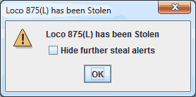
Ticking the checkbox before closing the popup will suppress loco steal notifications for the rest of the JMRI session, for all loco sessions.
Relevant information can be viewed in the main JMRI Console log.
Note that not all JMRI applications currently have a method for dealing with a stolen throttle.
Dispatch is available according to Command Station features.
Note that as dispatch availability for a single loco address may change, this will be reflected by button availability in the main JMRI Throttle.
Support for consisting depends on features of the connected hardware.
Although the CBUS protocol supports Advanced Consisting, this has not been implemented within JMRI at present.
JMRI Consisting : Advanced Decoder Consisting (Decoder Assisted Consist) is currently unsupported, hence this is set to Internal in the CBUS preferences.
Primary Address Consists are supported however.
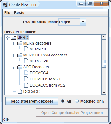
Subject to support in the connected hardware, a CBUS connection fully supports programming of decoders using DecoderPro and either or both service mode programming on a programming track and operations mode programming on the layout.
There are multiple ways to interface JMRI signalling with CBUS modules.
You are strongly advised to let JMRI control your signal logic, however it's also possible to link JMRI with 3rd party signalling over CBUS.
JMRI includes various signalling definitions, a popular choice for UK based layouts being BR2003, however for some layouts LMS 1932 or GWR 1931 may be more appropriate.
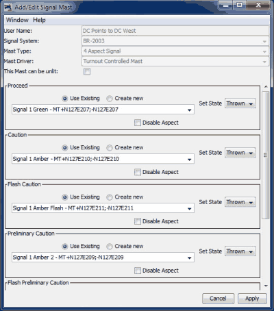
There are multiple ways of sending cbus events from JMRI out to LED or servo signal control modules, this is just one approach.
+N256E412 (only uses the ON event)+N256E416 (only uses the ON event)This ensures that only 1 CBUS message is sent for flashing aspects, specify this
flashing in the module board, not JMRI! Some Signal Mast types send 1 CBUS message for each
flash.
A layout with 20 quad aspect signals could send 40 odd cbus events every 0.5seconds, 4,800
events per minute. This could make network diagnosis awkward, although very unlikely to
swamp a CBUS network.
As stated previously, this is just one approach. There are other methods of interfacing JMRI with CBUS signalling systems.
There is initial support for the experimental CabData OPC available in JMRI CabSignals
This is normally done the other way round, however people may have existing systems in place which they do not want to change.
jmri.jmrix.can.cbus and jmri.jmrix.can.adapters .
CBUS is a registered trade mark of Dr Michael Bolton