This page describes how JMRI uses System Names to access CBUS-attached resources.
Suggestion from Mike Bolton :
His club has adopted the convention of 1 to 9999 for turnouts and 10000 upwards for
sensors.
This prevents the possibility of sending sensor events from their CANCABs (9999 max)
but they tie any relevant sensors to the turnout numbers e.g.
TO_1 is +1 and the feedback from this is +10001 for one way and +11001 for the other
way.
Using short events (or device numbers) this way makes life very simple with JMRI.
They control the turnouts from the CANCABs as well (also Smartphone throttles), this is
reflected in the JMRI panel and works a treat!
Their layout control panel is on a touchscreen monitor connected to a RPi 3B running JMRI,
with additional control panels through JMRI Web
Server.
Another use of event segmentation could be for modular club layouts, where various club
members building a section at home, then bringing it together into 1 big super layout.
Module 1 would have events 1,000 > 1,999 Module 2 would have 2,000 > 2,999 etc.
Suggestion from Pete Brownlow:
Pete uses pretty much exclusively long events.
For events sent from JMRI, he segments by node number that JMRI generates (for example,
node 99 for turnouts, node 98 for signals and node 97 for control sensors).
This makes it very easy to see what the events are for when looking at an event log.
For all input sensors from CBUS, he leaves the long event as generated by the CBUS module,
so it will retain the node number of that module, (eg; Node 256 event 1) so there's no risk
of generating the same event as a cab.
Because he doesn't use short events, there's no need to segment by the event/device number.
It also avoids the whole task of having to teach any producer events, just using what comes
from the modules by default.
You can invert the polarity of ON and OFF events
When JMRI is started, it doesn't presume that all sensors, turnouts and lights are active or inactive, they have an unknown status.
The vast majority of MERG module kits can send the current status of their inputs or outputs in response to a SOD event taught to that module.
JMRI can store cross-session information such as Memory Variables and Block Values ( Train Describer value )
When JMRI loads a panel, and the Track Power is on, block values from the previous session are loaded if the block is active.
It may make sense to set Track Power to Off on JMRI Startup and when a panel loads, switching the track power on after the panel has fully loaded.
JMRI DOES NOT attempt to create Sensor objects from the traffic that it hears on the CBUS network, unlike some other hardware systems.
This is because CBUS is essentially a networking protocol, not a sensor generator. Events are not intrinsically associated with specific hardware objects, people can use events in many ways.
You can request the status of a sensor by clicking Query in the sensor table.
CBUS is setup in JMRI for 4 types of turnout ( output ) feedback.
Turnouts have 2 states, the commanded state, and the Feedback state which is used on panel displays and elsewhere.
Turnouts are always in Monitoring mode hence reflect the commanded state from the
Layout.
In addition, feedback can be enhanced with
You can request the status of a turnout by clicking Query in the turnout table.
If a turnout uses 1 or 2 sensor feedback, these sensor statuses will also be requested.
See JMRI : Turnout Feedback for more info.
As Turnouts are JMRI outputs, the Event can be queried as per other MERG CBUS query
events.
If a Turnout has address "MT+4" and is closed, when JMRI hears an appropriate Event Status
Request ( eg. an ARSQ for Event 4 ), it will respond with an ARSOF 4 Can Frame.
This is used in modules such as MERG CANCAB to enhance the Toggle Turnout button, ie, if
the query returns OFF, CANCAB sends ON and vice-versa.
JMRI Reporters do not have Off or On events, they just use a device ( short event ) or node number.
Reporters are created by clicking the New button within the Reporter Table.
You can create multiple reporters by checking the Add Sequential Range option.
Like Turnouts Sensors and Lights, these are not created automatically in CBUS.
A typical system name for a reporter would be MR123 or MR1234
( no event On or Off ) .
The DDES and ACDAT OPC's are used for reporter data.
When an incoming DDES or ACDAT OPC is heard on the network, JMRI will look for a reporter matching the device or node number in the Reporter Table.
If a reporter exists, the ID tag within the 5 data bytes will be looked up from the ID Tag table.
If there's no matching ID Tag on the table, one will be created and updated.
If the ID tag was previously active for another reporter, the previous reporter will have the tag removed from its report.
Valid reporter numbers are minimum 0, to maximum 65535.
The DDES ( device number data ) and ACDAT ( node data ) messages are currently handled in exactly the same way, ie the first 2 bytes are used as the Reporter identifier.
This means that a reporter created via a number of 77 will respond to both DDES device 77 and ACDAT of node 77.
Reporters are saved in your main panel file, along with turnouts and sensors etc.
ID Tags cross-session automatically, no saving is necessary.
When adding an item to your JMRI Turnout Table, Sensor Table, Light Table or Reporter Table, a JMRI system name is automatically created from the hardware address you input.
This really is all you need to know to get started, the rest of the information on this page is aimed at advanced use cases, debugging panel xml files, and system development.
JMRI internally associates CBUS events with individual JMRI objects (Sensors, Turnouts, Lights, etc.) via the JMRI System Names.
Depending on which CBUS event IDs are used on a particular layout, these system names can get very long, in which case the "user names" are much more useful.
The 1st letter of a sensor, turnout or light system name is the JMRI system letter, generally "M" for MERG connections.
MS+123;-345" defines a Sensor that follows the "123 ON" and "345 OFF"
events to change state.
MT+123;-345
ML+123;-345
MR123
| In/Out | Entered as Hardware Address | Meaning | makes System Name | Mask | Equivalent | Min. | Max. | Notes |
|---|---|---|---|---|---|---|---|---|
| both | +18 | event 18 On; event 18 Off |
MT+18 | integer | +18;-18 | 01 | 65535 | SLiM Short Events ASON / ASOF |
| both | +N2E18 | Node 2 Event 18; On Event = Active; Off Event = Inactive |
MT+N2E18;-N2E18 | N1E1; N1E1 |
N 65535 E 65535 ; N 65535 E 65535 |
FLiM Long Events ACON / ACOF | ||
| both | +18;+21 | event 18 On; event 21 On |
MT18;21 | integer;integer | +18;+21 | 1 ; 1 | 65535; 65535 | |
| both | +18;-21 | event 18 On; event21 Off |
MT+18;-21 | idem signed | +18;-21 | |||
| both | X90002D002E;X91FFFFFFFE | hex CAN frame msg. Active; hex CAN frame msg. Inactive |
MTX90002D002E;X91FFFFFFFE | hex;hex | N/A | Depends on opcode | In eg. Thrown sends Long Event N 45 E 46 Closed sends Long Event N 65535 E 65534 |
|
| both | 200018 | Node 2 Event 18; On Event = Active; Off Event = Inactive |
MS200018 | node + (5 digits) | N2E18 | 100001 | 6553565535 | Current max. that can be entered (JMRI 4.12) is 2147483647 |
65,536 nodes and 65,535 events gives approx 4,294,901,760 event combinations.
65,535 is unrealistic for events within a node but does allow for useful segmentation of event ranges.
MERG module kits can use the whole CBUS range of event numbers, on a reset startup
operating in SLiM short event mode.
A MERG CANLED kit can support up to 255 taught events
A Sensor is defined by two events: The one that sets it ACTIVE, and the one that sets it
INACTIVE.
If these are mapped to ON and OFF frames with the same event ID number, respectively, only
the event ID number need be specified:
MS18 The number is decimal.
To increase versatility, it's possible to use different event ID numbers for the ACTIVE
transition (by default, an ON frame) and INACTIVE transition (by default, an OFF
frame):
MS18;21
The ON and OFF coding of CBUS is not entirely consistent with the event model,
it may be useful to connect the ACTIVE or INACTIVE transition of a JMRI Sensor to an OFF or
ON CBUS frame respectively.
Leading "+" and "-" characters can do this. For example,
MS-18;+21
defines a sensor that goes ACTIVE when an OFF frame with ID number 18 is received,
and goes INACTIVE when an ON frame with ID number 21 is received.
CBUS event numbers (usually) contain a node number in their most-significant bytes.
You can specify the node number either by using a full 5 decimal digits for the event
number itself, preceded by the node number:
MS200018
or by using the letters "N" and "E" to specify the separate parts:
MSN2E18
You can mask off part of the CBUS packet, so any values in the masked part will still
match, using the "M" format letter.
MS200018M07
"M" indicates the start of a hexadecimal mask that will be applied, where 1 bits in the
mask will be zero bits in the resulting value.
In the example above, "18" through "1F" will match.
This is particularly useful for matching e.g. CBUS short events, where parts of the packet
include the node number which should (usually) be ignored.
Hexadecimal numbering is based on the power of 16, using 0-9, then A-F.
CBUS modules communicate by messages with a fixed format: One byte of command and length information, followed optionally by additional data bytes.
In it's most simple form, this is used to send identifiable "events". In turn, events come in two types: "ON" and "OFF", with two forms, short ( SLiM ), and long ( FiLM ).
These are actually sent across a CBUS network in the form of an opcode, the command information.
There are 255 opcodes, the length of the data string following the opcode changes depending on which opcode is used.
There are multiple opcodes for events, Controlling and programming DCC devices, DCC consisting, Programming nodes with Node Variables, Programming nodes with events, Fast clock and temperature information, RfID reader data, and many more.
Four of these are the common opcodes for events :
| Ops Code Name ( MERG console log ) |
Decimal opcode |
Hexadecimal opcode |
|
|---|---|---|---|
| ASON | 152 | 98 | Short Event On |
| ASOF | 153 | 99 | Short Event Off |
| ACON | 144 | 90 | Long Event On |
| ACOF | 145 | 91 | Long Event Off |
It's possible to connect a Sensor to arbitrary CAN frames by specifying their data content as a hex string, indicated by "X".
This allows a Sensor or Turnout to disregard any intrinsic meaning to "ON" and "OFF" events, and allows it to respond to, or emit any frame on the layout.
These particular event opcodes use a Hex string 4 digits long, split into High then Low :
| Entered as Hex | Ops Code | Remaining Hex | Node Decimal | Event Decimal |
|---|---|---|---|---|
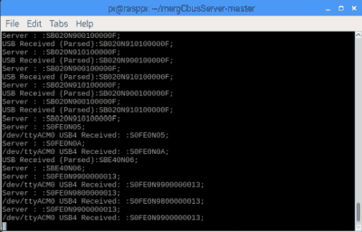
X9900000013
|
ASOF | 00 00 00 13
|
0 | 19 |
X980000002D
|
ASON | 00 00 00 2D
|
0 | 45 |
X980000BD2A
|
ASON | 00 00 BD 2A
|
0 | 48426 |
X990000FFFF
|
ASOF | 00 00 FF FF
|
0 | 65535 |
X9100130013
|
ACOF | 00 14 00 13
|
20 | 19 |
X90002D002E
|
ACON | 00 2D 00 2E
|
45 | 46 |
X90BD2BBD2A
|
ACON | BD 2B BD 2A
|
48427 | 48426 |
X91FFFFFFFE
|
ACOF | FF FF FF FE
|
65535 | 65534 |
Ensure you use the right opscode, eg if you include Nodes for a FiLM address, use ACON instead of ASON.
Sensors, Turnouts and Lights stored as Hex response events using the long and short
response OPCs will not be recognised as these are translated to standard on and off events
just before the ( sensor turnout or light ) internal message match check.
Apart from these specific OPCs, Sensors Turnouts or Lights can store any hex combination,
they need both an on and off side seperated by a ";".
The CAN frames can send CBUS opcodes in the hex form of the code you require.
eg, to set up a sensor to send ( DCC emergency stop / Track power on ) opcodes over
CBUS,
you could use a hardware address of X0A;X05
| Entered as Hex | Viewed in JMRI MERG CONSOLE | Viewed in CBUS SERVER | Ops Code |
|---|---|---|---|
X0A
|
[x[7f]0A]
|
S0FE0N0A;
|
(RESTP) Request Emergency Stop ALL trains A CBUS command station confirms request with an ESTOP 06 opcode. |
X05
|
[x[7f]05]
|
S0FE0N05;
|
(TON) Track Power On, normally broadcast from a command station |
All of these opcode messages are sent with the Standard CAN event frame, however the
protocol also allows for access to extended CAN frames.
These frames enable bootloading of modules ( firmware updates ), while future uses of this
may also be for local media streaming ( eg. transferring pictures of trains or sound files
between modules. )
The extended frames do not interfere with the standard frames, hence modules can be
targetted for boatloading by module number, without affecting normal layout messaging.
Extended CAN frames ( which are not CBUS messages ) can be monitored in the CBUS console, and are filtered from all other JMRI objects ( Sensors, Turnouts etc. ).
Module firmware updates are supported by the CBUS bootloader and by 3rd party software (FCU - FLiM Configuration Utility), available free for MERG members to download.
For advanced system development and packet proving, you may prefer to view the full packet across various applications, eg CBUS SERVER.
The JMRI CBUS
Console Tool can be very useful in seeing what is being sent across the network by the
hardware addresses you create.
The console is intended to be a tool to help users monitor packets using short and long
events, and may attempt to beautify the output.
Check the CBUS wiki and developers guide for more info and absolute specification.
The majority of opcodes according to the CBUS developers guide 6b are supported in some sort of form.
All outgoing JMRI CBUS messages have their OPC priority added to the header section of the message.
Many JMRI functions utilise the OPC support within :
There's a list of supported OPCs for each JMRI CBUS tool support page.
CbusSensor.java CbusSensorManager.java
CbusTurnout.java CbusTurnoutManager.java
CbusLight.java CbusLightManager.java
The flexibility in the hex form of creating Sensors, Turnouts and Lights allows any OPC to be sent, or received as an input.
When used as a short form address, eg "+N123E456" :
This does not currently include the extended data event OPC's.
CbusReporter.java CbusReporterManager.java
Messages sent from, and received by JMRI are handled the same by CBUS Reporters.
Received by JMRI when in internal programming state
Received by JMRI
CbusThrottle.java CbusThrottleManager.java
Messages sent by JMRI
Listeners for messages sent by JMRI
Listeners for messages received by JMRI
JMRI Scripting for CAN frames with CanExample.py
CBUS 3rd Party Links See link for the CBUS Developers Guide
CBUS® is a registered trade mark of Dr Michael Bolton