The Digitrax SE74 provides a variety of features which may be used with JMRI. JMRI-supported features include signal control, switch control, and inputs.
To do this, you open DecoderPro (as an individual application or via selecting "Roster" in PanelPro) and create a new roster entry. Select the Digitrax SE74 decoder type for it and enter the SE74's address. You can then use the usual DecoderPro panes to read and write the configuration variables (Op Switches) in the SE74.
Configuring the SE74's routes be done using the methods described in the Digitrax documentation for the SE74.
The SE74 has two mutually-exclusive operating modes which determine how JMRI can control the signal heads. As such, these instructions present two different ways of configuring JMRI to control the SE74 - one for each SE74 operating mode. One method is "SE8C-compatible" mode. The other is "Aspect" mode.
The "Turnout" mode of controlling signals makes use of Turnout control messages to convey the "aspect" information to the hardware. It operates in the same way as the SE8C device does, and JMRI support for this mode of operation is the same as when using the SE8C device.
Alternately, control of SE74 signal heads is via an "Aspect". This mechanism uses different LocoNet messaging than SE8C mode, and requires different support in JMRI. SE74 "aspect" mode signaling has a few benefits over SE8C mode. SE74 users are encouraged to make use of this mode of SE74 operation.
The SE74 offers an alternate mode for controlling signal head appearance. In the SE74 documentation, Digitrax refers to this mode as "aspect" mode. Control of each individual signal head is via DCC "Extended Accessory Decoder" packets. LocoNet-connected SE74 devices may get their control information directly from the LocoNet messaging, rather than from the DCC track signal.
The DCC "Extended Accessory Decoder" messaging uses an "address space" which is independent of the addressing used for turnout control messaging. As such, a turnout with address 260 does not conflict with a SE74 signal head at "aspect"-mode signaling address 260! This also makes it easier to configure SE74 addressing in a way that does not conflict with other "turnout"-type objects associated with the layout.
When an SE74 is operating in "Aspect" mode and it sees such a message which is addressed to one of its signal heads, it extracts the aspect number from the message and updates the addressed head to reflect the aspect associated with the aspect number. Note specifically that the "Aspect" mechanism Digitrax uses is controlled at the level of the "Signal Head". This design choice provides compatibility with some 3rd-party LocoNet signaling hardware. And it means that JMRI does not require SE74-specific support in its signaling implementation. It also means that changing the aspect of a mast which has more than one head can require more than one message to be issued when the aspect changes. (When a JMRI Signal Mast's aspect changes, the JMRI implementation will send a message to each Signal Head associated with the Signal Mast, regardless of whether the head aspect has changed).
This SE74 behavior is notably different from the behavior seen in some other signaling implementations. Some devices use a single single DCC extended accessory decoder control message to influence _all_ of the heads on the mast. That difference in hardware implementation and messaging usage means that configuring a JMRI Signal Mast using other hardware types will be different from configuring a JMRI Signal Mast for the SE74-controlled signal heads when the SE74 is configured for "Aspect"-mode signaling.
One of the SE74 signal control modes relies upon DCC Accessory Decoder (in other words. "Turnout") control mechanisms. The SE74 Instruction Sheet refers to this mode of operation in several different ways: "4 Turnout" mode, "SE8C Compatible" mode and "SW control" mode. For the purposes of this documentation, the use "SE8C" mode shall be used.
As is implied by one of those names used in the Instruction Sheet, this SE74 mode uses the same LocoNet messaging and mechanisms to control the signal head behavior.
When operating in "SE8C" signaling mode, the SE74 may be used JMRI when using any DCC system which supports control of turnouts from JMRI.
In the author's opinion, "Aspect" mode is preferred over "SE8C Compatible mode" for any system which can support "Aspect" mode.
This section describes how to associate a JMRI "Signal Head" object with the SE74 hardware and one of its controlled Signal Heads, when the SE74 is configured to use "Aspect"-mode signaling. This section does not apply when the SE74 is configured for "SE8C"-mode signaling; see this section for information on configuring JMRI Signal Head objects when using the SE74 in "SE8C"-mode.
It is assumed that you have JMRI configured to communicate with your DCC system, and that you have configured the SE74 for "Aspect" mode signaling and that the SE74 has a base address which does not conflict with any other aspect-mode signaling hardware. With those assumptions met, you may start configuring the JMRI "Signal Head" objects.
Within the JMRI Panel Pro application, open the Signal Heads" table (i.e. Tools ⇒ Tables ⇒ Signal Heads ). This table shows all the Signal Heads which have been defined.
To configure a new JMRI "Signal Head" object, it is necessary to "add"
a signal head. This is done by activating the "Add" button at the bottom
of the Signal Heads table. This will open an "Add Signal Head" window,
where the specific information required to define a signal head may be
entered. An example image is shown below.
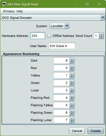
Aspect Mode Hardware Address = (SE74 base address) + ((SE74 head number) - 1)
Note that there is no JMRI requirement to select a user name that mentions the Digitrax "head letter", except that it will be easiest to wire and debug if you leave yourself sufficient hints. Those hints may be left in the user name, in the "comments", or may be left out of the JMRI information altogether at the user's choice. If you are able to compute the connector number and Digitrax "head" letter from the "head" address and the SE74 base address, you may not need such hints.
Note also that the SE74's "aspect-mode" signaling provides a SE74 setting where the "Lunar" aspect may be made "persistant". JMRI is not able to understand the concept of a "persistant" aspect capability, so that feature needs to be disabled in the SE74's OpSw settings.
It is assumed that you have JMRI configured to communicate with your DCC system, and that you have configured the SE74 for "SE8C Compatible" mode and that the SE74 has a base address which does not conflict with any of your other hardware. With those assumptions met, you may start configuring the JMRI "Signal Head"s.
Within the JMRI Panel Pro application, open the Signal Heads" table (i.e. Tools ⇒ Tables ⇒ Signal Heads ). This table shows all the "JMRI Signal Heads" which are defined within JMRI. A JMRI "Signal Head" provides a mechanism for JMRI to interact directly with a single signal head.
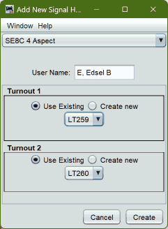
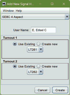
Set up each individual signal head by "add"ing a signal head. This is done using the "Add" button at the bottom of the Signal Heads table. This will open an "Add Signal Head" window, where the specific information required to define a signal head may be entered.
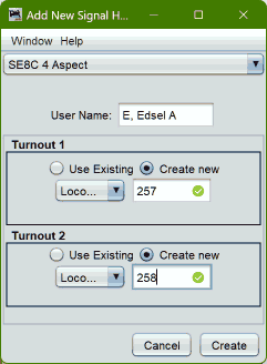
"Turnout 1" hardware address = SE74 base address + ( 2 * ( SE74 head number + 1 ))
"Turnout 2" hardware address = SE74 base address + ( 2 * ( SE74 head number + 1 )) + 1
Extending the example above, a three-head mast would require two
additional head definitions. If the additional heads are to be configured
to be the next two heads on a SE8C-mode SE74, they would be defined as
shown in the images below.
Once you have defined your signal head(s), and you have your signaling hardware connected, you should verify that the JMRI Signal Heads actually control the signal hardware appropriately. You may check this by verifying that the physical signal head is actually displaying the aspect which is shown for that signal head in the Signal Heads table's "Appearance" column.
Note that JMRI supports displaying "flashing" aspects on SE8C-mode signal heads, but it does not support the SE8C's "Flashing Aspect" feature, and therefore does not support the SE74's equivalent feature. Be sure that the SE74's "fourth aspect" setting specifies "Dark" as the fourth aspect.This limitation was intentionally chosen by JMRI designers because the SE8C "flashing aspect" feature would only be able to support one flashing color. That limitation is inconsistent with many prototypical signaling systems. Instead, JMRI developers chose to make use of "dark" for the "fourth aspect" as the fourth aspect, as JMRI could then control the head's turnouts in appropriate patterns in order to achieve "flashing" aspects for any of the head's colors.
Once you have configured one or more JMRI "Signal Head"s defined, you may then create one or more JMRI "Signal Mast"s which use those configured heads. Configuring JMRI Signal Mast objects is necessary for several forms of JMRI-controlled signaling, especially for JMRI "Signal Mast Logic"-based signaling.
Creating a JMRI Signal Mast object using one or more JMRI Signal Head objects allows JMRI to hide any differences in Signal Head implementations at the Signal Head level. That means that defining the Signal Mast is independent of the SE74's signaling mode setting - if you have configured the JMRI Signal Heads in a way which matches the SE74 signaling mode, then the JMRI Signal Mast simply uses the Signal Heads, and "gets it right" automatically.
The image below shows how to configure a JMRI Signal Mast when the mast is controlled via JMRI "signal head" objects.
The mast being defined is a three-head Searchlight mast using the AAR-1946 "signal system", and will be used at "East Edsel". The specified "User Name" was chosen to describe the location of the mast, and is chosen to included the word "Mast" to help differentiate the Signal Mast's User Name from the User Names used for the Signal Heads. If there were any other masts at East Edsel which governed movement in the opposite direction, then it would be appropriate to include some sort of "direction" in the user name, such as "E. Edsel WWD Mast", where "WWD" is an abbreviation for "WestWarD".
The mast comprises the three signal heads - the three "SE8C-mode" SE74 signal heads defined above in the section on defining SE8C-mode SE74 signal heads. Note that if the mast were comprised instead of three "aspect- mode" SE74 signal heads, the mast definition would not be any different - it would simply use the appropriate signal head "user name"s.
Also note that two "aspects" have been disabled - aspects associated with
"Limited Speed" indications, because in this example, the trackwork at
East Edsel does not have any route which supports the "Limited" speed, so
those aspects are not allowed to be displayed by this mast.
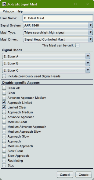
To create such a mast, the following steps are necessary:
In the example, the mast will always be "lit", because the "This mast may be Unlit" feature has not been enabled (has not been "check-marked"). This choice makes sense for the type of signaling which is being implementing for this mast. Other masts might make use of the "Unlit" feature, perhaps for so-called "approach lighting".
Once the JMRI Signal Mast has been configured, any change to the signal mast's "Appearance" will cause the associated JMRI Signal Head object(s) to be changed to the individual head aspect(s) to match the mast's definition for that aspect. Any such Signal Head aspect change(s) will be propagated, under the JMRI "Signal Head" object's direction, to the appropriate signaling hardware (in this case, the SE74), so that the hardware may update its outputs based on the control information which has been conveyed to it.
This means that you can test the JMRI configuration of your SE74 hardware using the following techniques. (They also apply to other signaling configurations, too!)
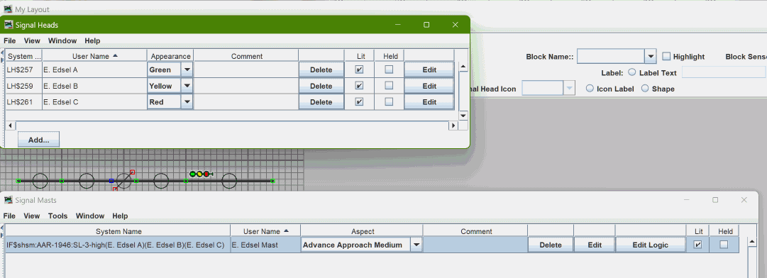
Note that any change to the "Appearance" value for an individual Signal Head object will propagate to the appropriate hardware, but a change of a JMRI Signal Head object's Appearance will not propagate to a JMRI "Signal Mast" object. This is a characteristic of the implementation of the "Signal Head Controlled Mast" type of JMRI Signal Mast.
JMRI may control the SE74's "turnout" outputs just like it controls any other Turnout - via a JMRI "Turnout" object. In general, JMRI Turnout objects are defined in the JMRI "Turnouts" table, and are discussed elsewhere.
JMRI's LocoNet mechanisms provide a mechanism where JMRI can "discover" LocoNet-connected turnouts. That mechanism is able to discover SE74-related turnout objects, and will do so when the SE74 is powered and is connected to LocoNet when JMRI starts up with a live connection to that LocoNet.
While the SE74's inputs may be used with JMRI, the behaviors of the SE74s inputs, at least for SE74 firmware versions available to the date of this writing, are "odd". In general, the SE74 input pin behaviors do not match the behaviors of any previous Digitrax product. The SE74 "SWx" input pins "sort-of" behave like the similarly-named DS64 input pins do when the DS64 is in configured one way. The "SENSx" pins "sort-of" behave like the "AUXx" DS64 input pins do for other DS64 configurations.
With SE74 firmware implementations available in early 2023, the "default" values of SE74 OpSws 11 and 30 result in the SENSx input pins generating LocoNet messaging which is suitable for "general-purpose" sensor input. Those inputs will be reflected as four JMRI "Sensor" objects, with sensor hardware addresses of:
| Sensor | Hardware Address |
|---|---|
| SENS1 | hardware address = (2*(SE74 base address)) - 1 |
| SENS2 | hardware address = (2*(SE74 base address)) + 1 |
| SENS3 | hardware address = (2*(SE74 base address)) + 3 |
| SENS4 | hardware address = (2*(SE74 base address)) + 5 |
Some examples include:
| Base Address | Input | Hardware Address |
|---|---|---|
| 253 (factory default) | SENS1 | 505 |
| SENS2 | 507 | |
| SENS3 | 509 | |
| SENS4 | 511 | |
| 254 | SENS1 | 507 |
| SENS2 | 508 | |
| SENS3 | 511 | |
| SENS4 | 513 | |
| 255 | SENS1 | 509 |
| SENS2 | 511 | |
| SENS3 | 513 | |
| SENS4 | 515 |
The SE74 provides "route" functionality, where each of 8 routes may be configured with a "trigger" switch control, and up to 7 additional switch control messages to send when that trigger switch control is seen as a message on LocoNet. JMRI does not have a tool for configuring the SE74's "routes" functionality at this time. Instead, use the mechanisms described in the SE74 manual.
JMRI may trigger an SE74 route by sending a LocoNet switch control message which matches the "trigger" entry for any one of the routes configured in the SE74.
LocoNet® is a registered trademark of Digitrax, Inc.