Hardware Support: LocoIO
A LocoIO board is a DIY stationary interface to LocoNet for up to 16 input/output pins.
More on the available configuration options below.
The original LocoIO design by John Jabour was further
developed by Hans Deloof.
To access a list of all active LocoIO modules (and select one to program), turn on the layout and power up the
LocoIO hardware. No jumpers or buttons on the LocoIO need touching in order to proceed.
Select Manage LocoIO (LNSV1)
Modules from the LocoNet menu to open the tool. Click [Probe All] if the list is empty.
Programming a LocoIO family board
Since JMRI 4.21.2
The Public_Domain_HDL_LocoIO
Decoder Definition in the "Public Domain and DIY" category supports set-up of a wide range of
LocoIO devices up to LocoIO/LocoBooster/LocoRCD/LocoServo rev 1.54 hardware since 2020.
To program a LocoIO module, follow these steps:
- Turn on the layout and power up the LocoIO hardware. No jumpers or buttons on the
LocoIO need touching in order to proceed.
- Open DecoderPro main roster view or the Roster menu option in PanelPro.
- Click on the [Program] button in the last cell of a row in the LocoIO Tool.
Create a new entry if the board shows up in the list but the button reads [No Entry in Roster] by
clicking the [Add New Loco] button at top left of the main Roster.
- In the Decoder Installed box, navigate to "Public-domain and DIY" > "Hans Deloof
LocoIO".
- Looking at your hardware, select the correct PIC programmer firmware version from the
list. It is often labeled on the biggest IC chip. If your version is not in the list,
select the first higher one. In this example we pick "LocoIO v1.53":
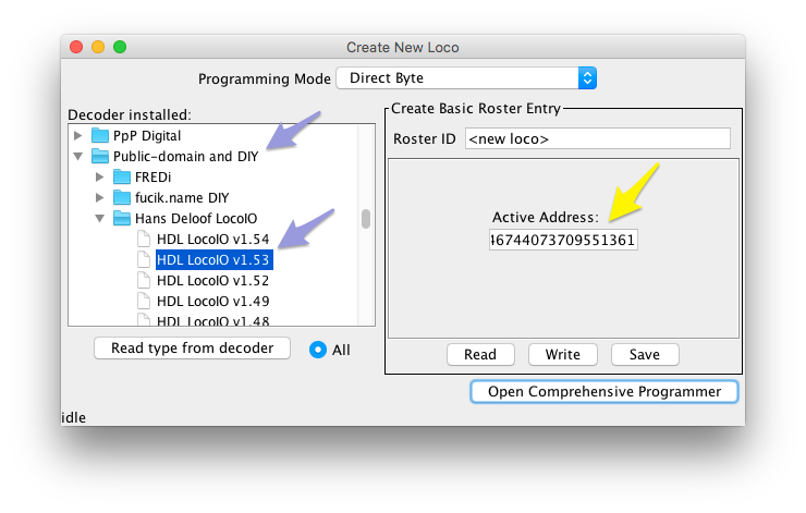
- On the right of the Create New Loco pane, enter a name for this module, eg. "LocoIO
81/1 rev 1.53", and fix the ultra-long decoder DCC address suggested. We chose 81, the
factory default board address:
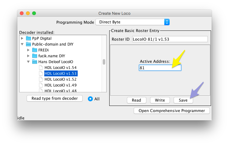
Click [Save] and close the Create New Loco pane.
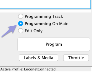
- You will see the new entry appear in the Roster.
Select it, make sure to select Programming on Main, and click [Program]:
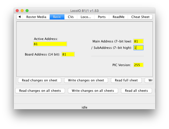
- On the Basic tab, enter the actual LocoIO Main Address and Sub-address, "81" and "1"
respectively in our example:
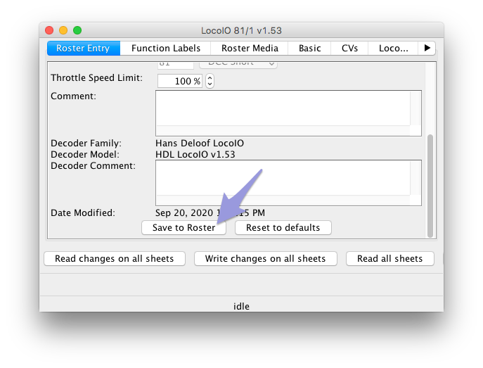
- Next, go to the Roster Entry pane, click [Save to Roster] and close & reopen the LocoIO
definition from the Roster to update the actual decoder address:
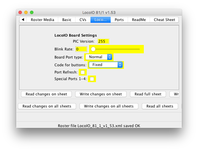
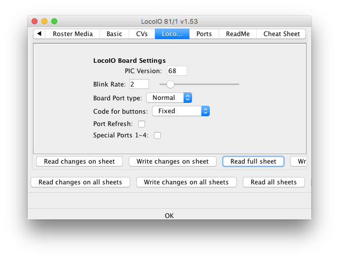
- Returning to the Basic tab, click [Read full sheet]. If a LocoIO is found at the
address, its firmware version is displayed (the Monitor LocoNet window will show more
precise information regarding the firmware).
- Warning: If you wish to change the address of a LocoIO board, you
MUST first ensure that ONLY a single LocoIO-based board is connected to the
LocoNet, as the address is set via a broadcast message.
If you Write CV2 and CV3 on the CVs tab or press [Write All] from the Basic tab,
ALL LocoIO's on your LocoNet will be reprogrammed with the same new
address.
-
-
-
-
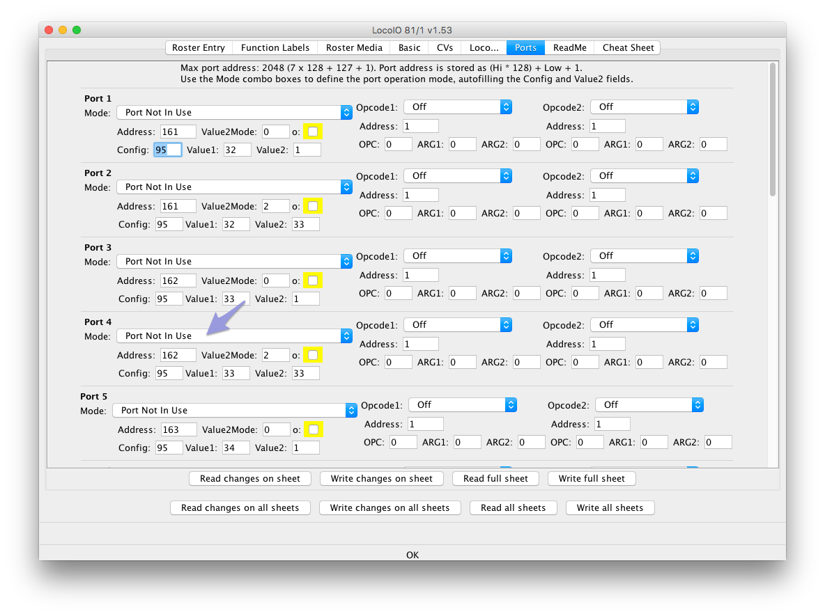
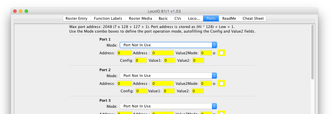
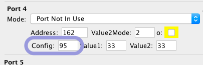
- After Read All, many ports will show a Mode selected. Due to the complexity of the
LocoIO memory DecoderPro can't figure out some choices, so you will have to assist at this
point for those ports that still show "Port not in Use". At least you will notice the
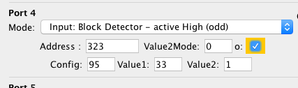
numbers already changed. For example on Port 4 the number in the Config field reads
"95":
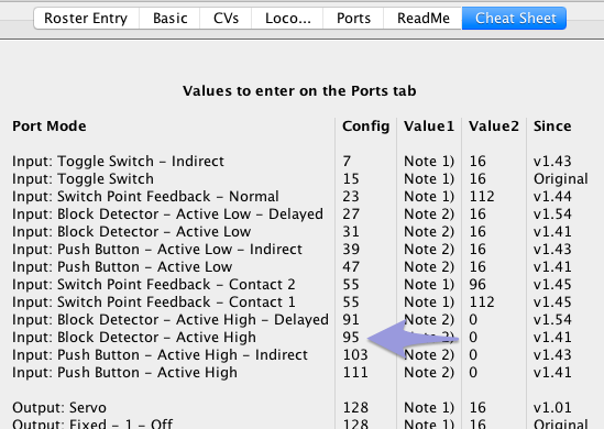
- Turn to the Cheat Sheet tab reference, in the Config column look up "95". It's a
Block Detector - Active High:
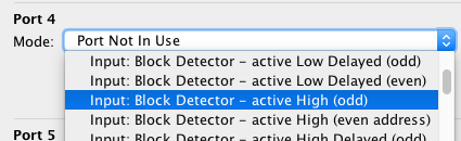
- Return to the Ports tab and in the Port 4 Mode combo, pick "Block Detector - Active
High" (either odd or even address, will correct automatically later on):
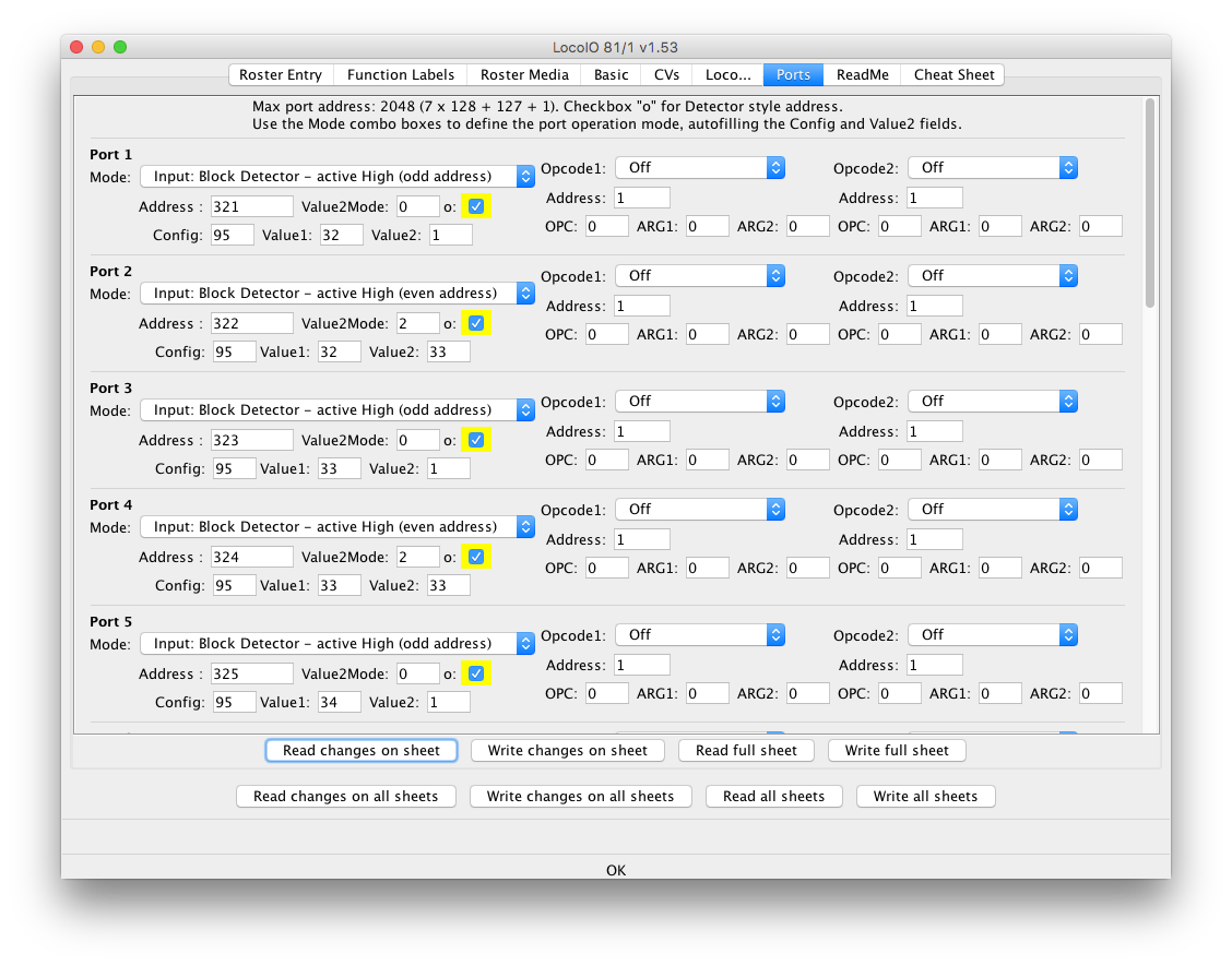
- After clicking [Read changes on sheet]:
- After fixing all mode combo's that are not "0", once again click [Read full sheet] to
update all fields and inspect the LocoIO configuration. Scroll down to see more ports:
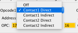
- Inputs allow setting up to two more actions carried out when the pin goes to ON. You
can set the action type and the address on the right hand side of the LocoIO programmer
pane as shown here. See the HDL documentation for examples and further information:
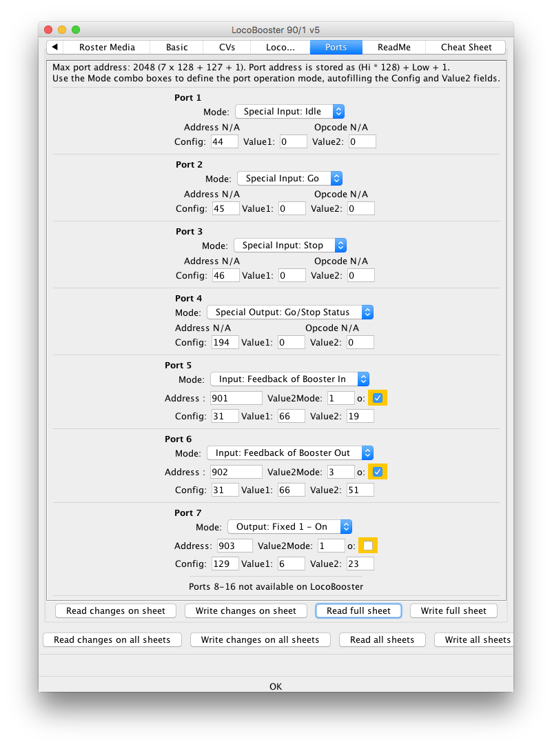
- A LocoBooster module will show several special options:
LocoIO Port Configuration
A typical LocoIO board contains 16 signal pins, also called channels or ports. Each port can be
individually programmed as input (fascia pushbuttons, turnout feedback or occupancy sensors) or
as output (fascia indicator LEDs, signal LED's, turnout motors etc.) and perform a number of
different things (depending on the module's hardware and firmware version):
Options for LocoIO Inputs:
- Block Detector - Active Low
- Block Detector - Active High
- Block Detector - Active Low - Delayed
- Block Detector - Active High - Delayed
- Push Button - Active Low
- Push Button - Active Low - Indirect
- Switch Point Feedback - Normal
- Switch Point Feedback - Contact 2
- Switch Point Feedback - Contact 1
- Push Button - Active High - Indirect
- Push Button - Active High
- Toggle Switch
- Toggle Switch - Indirect
Options for LocoIO Outputs
- Fixed - 1 - Off
- Fixed - 2 - Off
- Fixed - 1 - On
- Fixed - 2 - On
- Pulse - 2 - Soft Reset
- Pulse - 1 - Soft Reset
- Pulse - 2 - Hard Reset
- Pulse - 1 - Hard Reset
- Fixed - 1 - Off - Blink
- Fixed - 2 - Off - Blink
- Fixed - 1 - On - Blink
- Fixed - 2 - On - Blink
- Fixed - 1 - Off - 4-Way
- Fixed - 1 - Off - 4-Way - Blink
- Fixed - 2 - Off - 4-Way
- Fixed - 2 - Off - 4-Way - Blink
- Fixed - 1 - On - 4-Way
- Fixed - 1 - On - 4-Way - Blink
- Fixed - 2 - On - 4-Way
- Fixed - 2 - On - 4-Way - Blink
- Block (Occupancy) Detector
- Block Detector - Blink
- Servo (LocoServo ports 5-12 only)
Since LocoIO rev 1.49
- Port Not In Use
- On older boards, you are advised to configure unused ports as Output Fixed to prevent
accidental signals
See the Cheat Sheet included in the DecoderPro LocoIO Programmer for further details.
The ports are configured via LocoNet LNSV1 messages, but the DecoderPro Programming interface
takes care of many technical details. Documentation is included below and in the decoder
definition file.
Third Party info
- Since JMRI 5.11.3There is an Arduino Nano based DIY LocoIO, see GCA50a. Based on this design, a
dual RFID reader GCA51 is also supported in JMRI.
- For more information on the HDL LocoIO and how to use the boards, see LocoHDL.
- A copy of the original LocoIO DIY project description is available courtesy of www.rr-cirkits.com
LocoIO History
The initial LocoIO provided the following pin options:
- "Toggle switch controls turnout"
-
Generate a OPC_SW_REQ to close/throw a turnout when a toggle switch changes state.
When the input goes high, a "close" command is sent; when the input goes low, a "throw"
command is sent. The channel configuration value is 0x0F.
- "Input low flips turnout"
-
Generate a OPC_SW_REQ LocoNet message when the input goes low. This is intended for
use with a momentary pushbutton. The command sent will alternate the position of the
addressed turnout or signal; if "close" was last sent, a "throw" will be sent now and
vice-versa. The channel configuration value is 0x2F.
- "Input high flips turnout"
-
Generate a OPC_SW_REQ LocoNet message when the input goes high. This is intended for
use with a momentary pushbutton. The command sent will alternate the position of the
addressed turnout or signal; if "close" was last sent, a "throw" will be sent now and
vice-versa. The channel configuration value is 0x6F.
- "Status message sets output"
-
Drive an output from OPC_INPUT_REP input status messages on the LocoNet. The output
goes high when an "input high" message is received, and goes low when an "input low"
message is received. These messages are also used for block occupancy status; the
output will go high when the block is occupied, and low when its empty. The channel
configuration value is 0XC0.
- "Turnout close cmd sets output"
-
Drive an output on the LocoIO board from received OPC_SW_REQ commands. The channel
configuration value is 0x80. This adjusts the address field to look for a command that
sets the turnout "closed".
- "Turnout throw cmd sets output"
-
Drive an output on the LocoIO board from received OPC_SW_REQ commands. The channel
configuration value is 0x80. This adjusts the address field to look for a command that
sets the turnout "thrown".