As indicated on the PanelPro introduction page, there are several editors within PanelPro and a significant number of other tools that supplement and build upon PanelPro content. This page provides an overview of creating a layout editor panel with turnout control, block detection and signaling.
The goal is to provide an introduction to the main PanelPro tables while creating a Layout Editor panel. When done, the panel and its table data provide the foundation for other PanelPro activities such as creating a CTC panel, using Entry/Exit, using Dispatcher to run trains, or building a separate panel using Control Panel Editor to use Warrants.
While this is a term from the NMRA LDSIG (Layout Design Special Interest Group), it helps to set the stage.
A GettingStarted.zip file is available for download and contains a JMRI profile with panel xml files. These are provided for reference and can be used to practice the getting started steps. The appropriate file name will be indicated by a specially formated paragraph.
Demo panel: <file name>
Download the zip file and unzip it. Use the OS file manager to move the resulting profile and its contents to the settings location. When starting JMRI, select the GettingStart profile. If the profile selector is not active, use Preferences ⇒ Config Profiles to select the profile.
The settings location is an OS specific location that provides access to the user data.
The first time PanelPro is started, a connection must be defined. For this exercise the Digitrax LocoNet Simulator will be used.
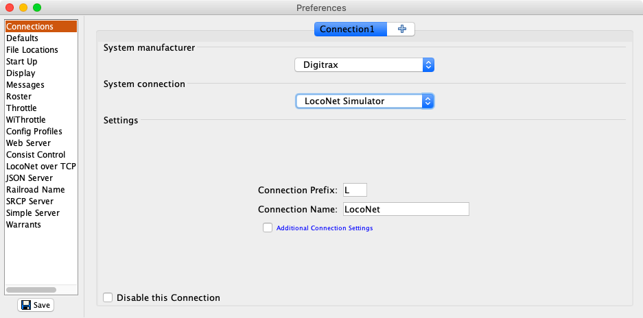
Detail help: Connections
Add the JMRI System Console as a startup action. When something is not working as expected, having the system console available makes it easy to see if there was an error or a warning. The error might not make sense, but using the Copy to clipboard button makes it easy to include the content in a posting to the JMRI users's group at groups.io: JMRI Users Group.
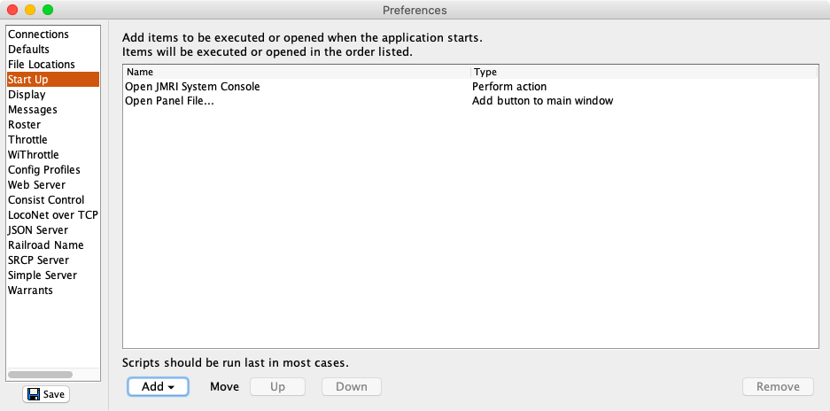
Detail help: Start Up Actions
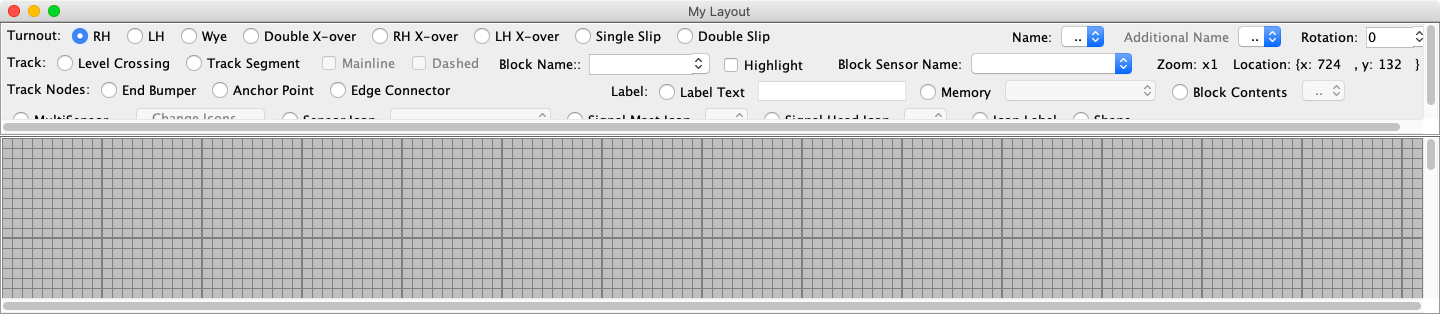
When PanelPro Panels ⇒ New Panel ⇒ Layout Editor is selected, a blank panel will be created with a default name. The panel will fill the screen, it will have a grid and at the top will be the Layout Editor tool bar.
Detail help: Layout Editor
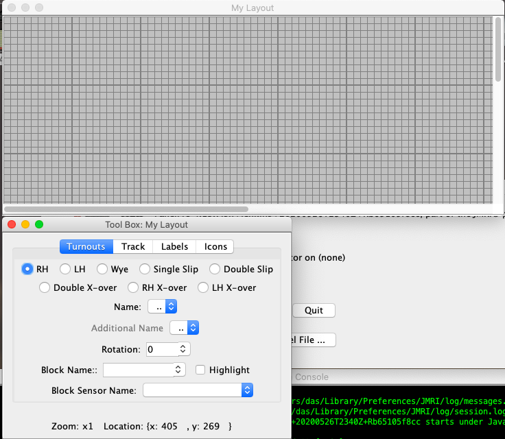
As the panel is switched between edit and display mode, the tool bar is shown/hidden and the panel shifts. Layout Editor Options ⇒ Toolbar ⇒ Toolbar Side ⇒ Float provides a floating tool box that avoids the shifting behavior. The tool box can be closed or minimized. To re-open the tool box use the Window menu (next to Help). The window name will start with Tool Box: followed by the panel name.
Click on Layout Editor Options ⇒ Show Help Bar in Edit Mode. This will add a help bar to the bottom of the panel window or the floating tool box. It shows the mouse and keyboard actions to add and move layout components. The third line changes based on the operating system. The image shows the macOS version.

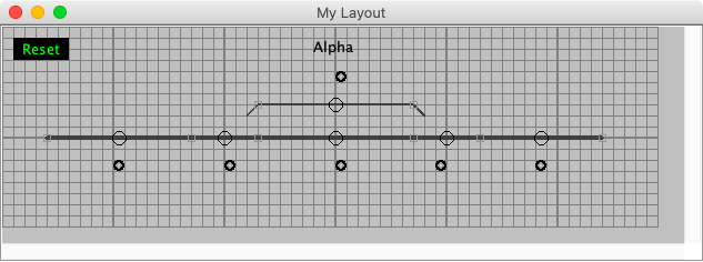
The track plan is a short stretch of track with 2 turnouts and a siding.
Add a left hand turnout and a right hand turnout to the panel. Rotate the right hand turnout 180 degrees, add two end bumpers and draw the track between the connection points. The demo uses the mainline option for the main track. When the connection points turn green, they are valid.
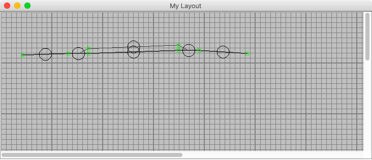
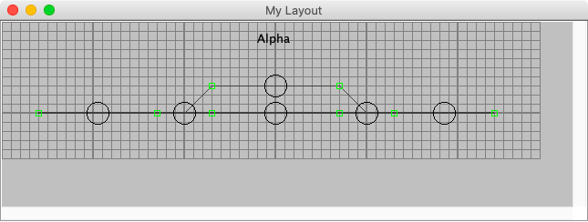
Clean up the track plan by moving components to the grid. The snap to grid settings for adding and moving items can be set using Layout Editor Options ⇒ Grid Options. The diverging legs of the turnouts have been extended at a 45° angle. A label has been added to provide a name for the siding. Everything on the prototype has a name.
The track, as is, does not do much. It needs to create and respond to layout events. The primary events are setting turnouts and responding to block occupancy. The implementation of these events is based on the layout connection and related hardware.
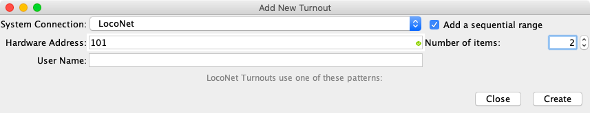
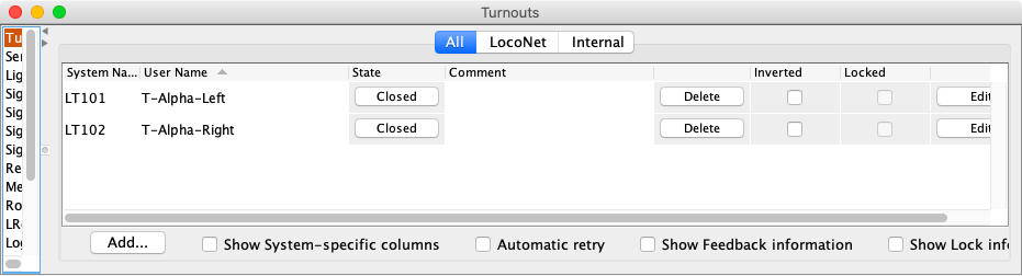
Turnouts are defined using PanelPro Tools ⇒ Tables ⇒ Turnouts. Click on Add. Two turnouts are defined and assigned user names: T-Alpha-Left and T-Alpha-Right.
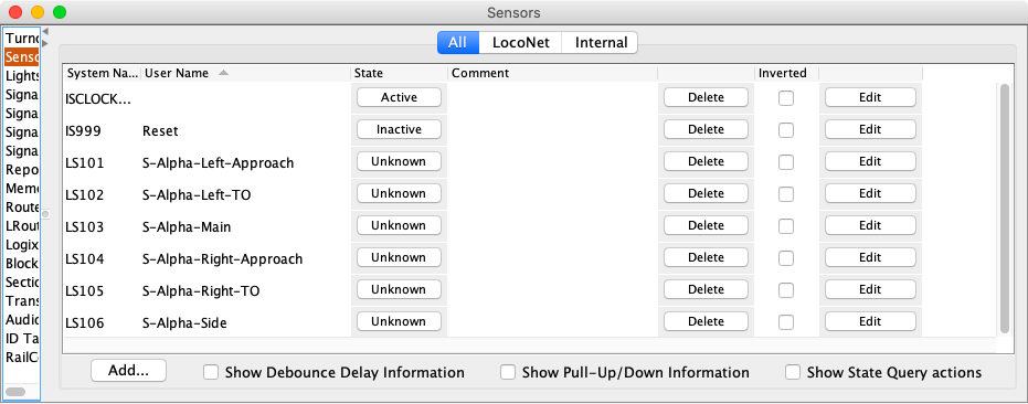
Sensors are defined using PanelPro Tools ⇒ Tables ⇒ Sensors. Click on Add. For now, create one Internal sensor with an address of 999 and Reset as the user name. This will create a sensor with a system name of IS999.
Note: The Reset sensor is Internal because it is not physically on the layout. It is used for internal JMRI purposes. It could easily be a physical push button on the layout. Then the system name would be LS999.
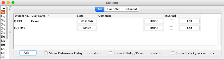
Since the connection is simulated, setting the initial value helps with testing later on.
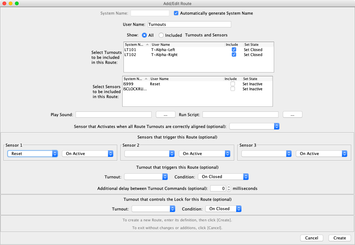
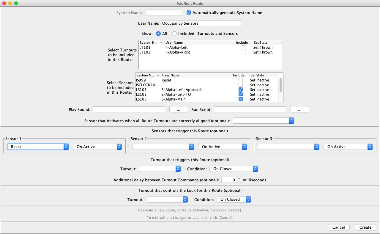
Routes are defined using PanelPro Tools ⇒ Tables ⇒ Routes. Click on Add. Select Automatically generate System Name, enter a Route user name, select the two turnouts and set the state to Close. Select the Reset sensor from the Sensor 1 list. Click on Create.
A LRoute is stored as a Logix. There is a special LRoute know as a RTXINITIALIZER. The Logix created by this LRoute is the very first Logix invoked after loading a data file. This makes it perfect for doing the initial setup.
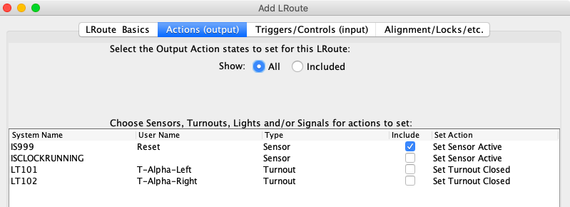
Use PanelPro Tools ⇒ Tables ⇒ LRoutes. Click on Add. Click on the Actions (output) tab, select the Reset sensor and set the state to Active.
Click on the LRoute Basics tab, enter a name in the user name field and select the Initializer option. Click on Create.
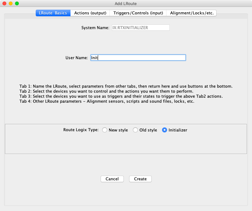
When the data file is loaded, the RTXINITIALIZER Logix will set the Reset sensor to Active which will trigger the Turnouts route which will set the turnouts to Closed.
Add the Reset sensor to the panel using the toolbar Sensor Icon option. Use the right click context menu to change the sensor to Momentary.
The next steps are going to convert the sensor icon into a clickable label. This can help save space on the panel. Use the right click context menu Change To Text item and then the Properties item.
Set the Active and Inactive Font and Background colors.
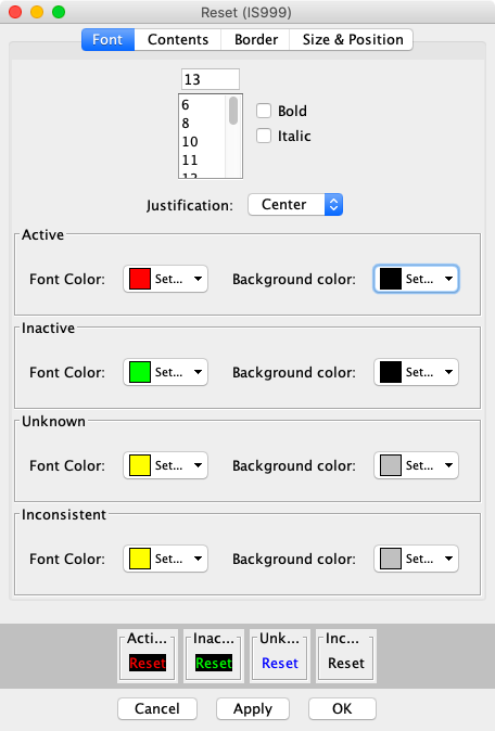
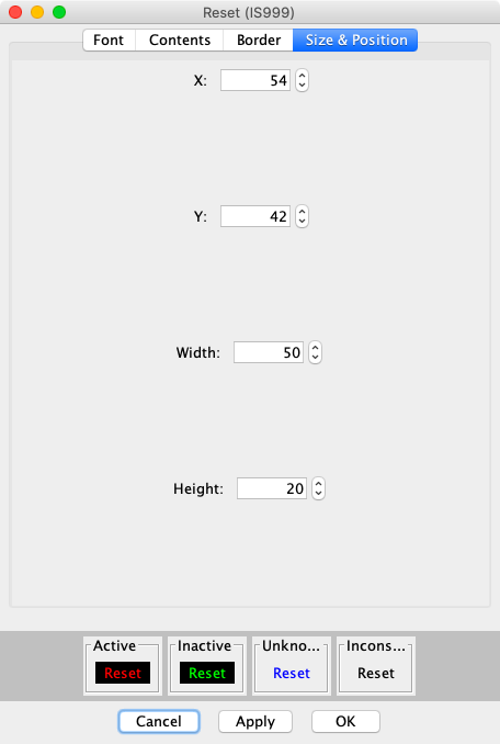
Select the Size & Position tab, set the Width and Height. As the width and height are changed, the preview boxes at the bottom will show the current results. This helps to insure that the resulting labels are acceptable.
Demo panel: GS-1-Basic Track Plan.xml
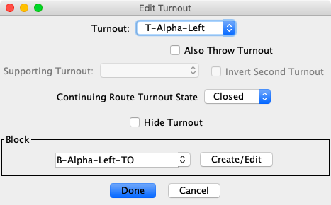
Right click each turnout to get the context menu and select Edit. Select the turnout name and type the block name in the Block field. Click Done. The Block table entry will be automatically created.
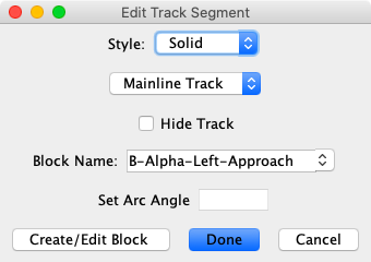
Repeat the block assignment process for each track segment.
Demo panel: GS-2-Blocks.xml
Go to the sensor table and create six LocoNet sensors in the sensor table. Assign user names based on the block names.
Go to the route table and create a route table entry to initialize the occupancy sensors to Inactive. Select the Reset sensor from the Sensor 1 list. Click on Create.
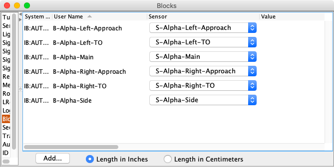
Use PanelPro Tools ⇒ Tables ⇒ Blocks to assign the occupancy sensors to each block. The blocks were automatically created when the block names were assigned using the Layout Editor Edit dialog for each piece of track. To simplify the process, drag the Sensor column next to the User Name column.
Add the occupancy sensors to the panel. The sensors on the panel are used to simulate train occupancy. They can be used to see how the track responds to occupancy changes. They will be used later to validate the signal mast logic.
If desired, there is a context menu item to Hide when not editing. This can be used to reduce clutter on the screen when not in edit mode.
Position them near the appropriate track block.
Demo panel: GS-3-Panel Sensors.xml
The basic panel is now done. It has turnouts, occupancy sensors and blocks. It can simulate sending turnout commands to the layout and respond to simulated occupancy changes. It includes the ability to initialize the layout after panel loading using Routes, LRoutes and Logix.
The above link provides an overview of signaling support in JMRI along with links to specific topics.
The sample layout will be using signal masts based on the Basic signaling system. The selected signaling system provides the aspects, the appearances of signal masts, their icons, and the rules for determining the signal mast aspect. JMRI provides signaling systems for many prototypes. The logic to set the mast aspects will be done using signal mast logic (SML).
A signal mast protects the trackage beyond the signal mast up to the next signal mast. Signal masts are placed at block boundaries. This means they are protecting one or more blocks which can contain turnouts.
The turnouts on the panel at Alpha have their own blocks which means they provide 3 block boundaries. The two end bumpers are also considered block boundaries. Block boundaries can also occur at level crossings, anchor points and edge connectors. Most layouts are not large enough to have long mainlines with intermediate signals.
Signal masts are created using PanelPro Tools ⇒ Tables ⇒ Signals ⇒ Signal Masts.
Select Add to create a new signal mast.
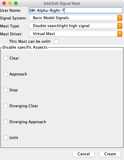
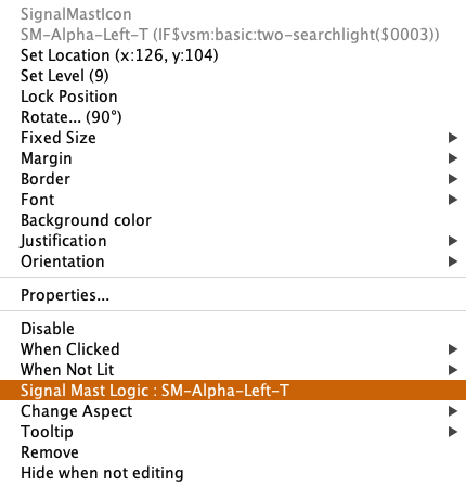
The User Name: can be anything. In this example, the entered name indicates that the signal mast is related to the right turnout at Alpha and will be placed at the throat (T) of the turnout. The suffixes for the signal masts at the frog end will be C for the straight leg (Continuing) and D for the curved leg (Diverging).
The Signal System: is set to Basic Model Signals. The list contains signal systems for many prototype railroads.
After the signal system has been selected, the Mast Type: list will be changed based on the selected signal system. Select the appropriate mast type. For the turnout throat the Double searchlight high signal will be used. The frog end masts use the Single searchlight high signal type and the end bumper masts will use the Single searchlight low signal type.
The selected Mast Driver: controls how the signal mast aspect information is sent to the layout. The appropriate driver will depend on the signaling hardware that has been installed on the layout. There is also a Virtual Mast driver that can be used when there are no signals on the layout or the decision for the layout hardware is still pending.
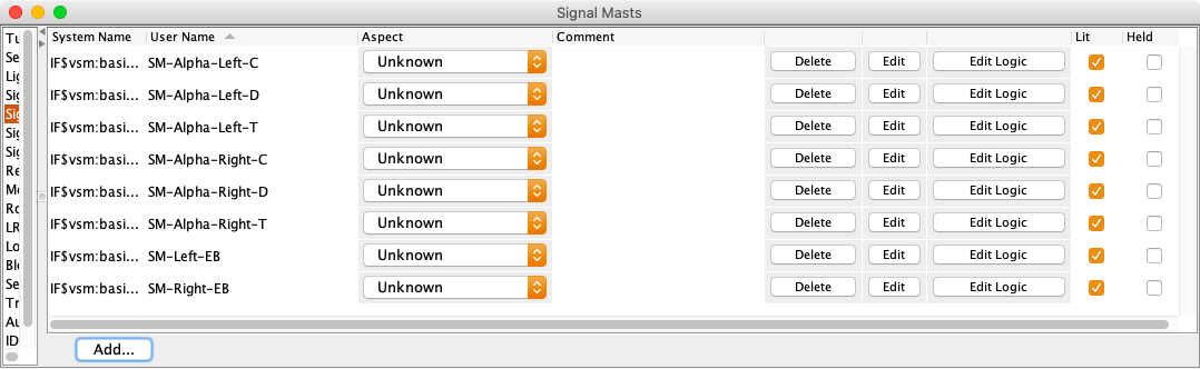
The signal mast table now contains 8 signal masts
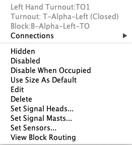
The Layout Editor Toolbar has a selection for adding signal mast icons to the panel. This results in an unconnected icon that is not related to any block boundary. The proper method is to use the Set Signal Masts item from the context menu. Right click a turnout, level crossing, end bumper, anchor point or edge connector that forms a block boundary. If the block boundary is valid, there will be an entry for Set Signal Masts.
A dialog will be displayed with combo lists for selecting masts and options for placing the masts on the panel. Each box identifies the blocks that form the boundary. This helps with choosing the proper signal mast.
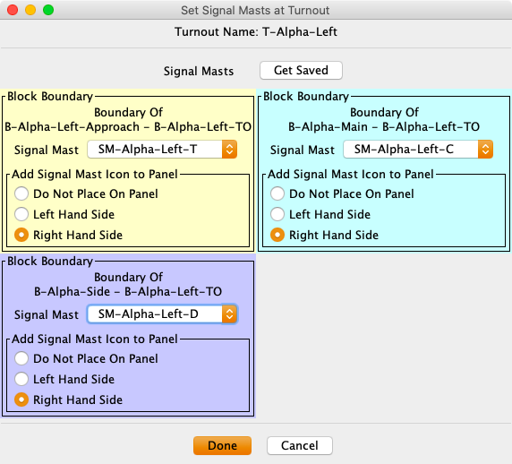
The number of boxes depends on the number of block boundaries. Standard turnouts ( LH, RH, Wye) can have up to 3. Crossovers and level crossings can have up to 4. Anchor Points and Edge Connectors will have two and End Bumpers will have one.
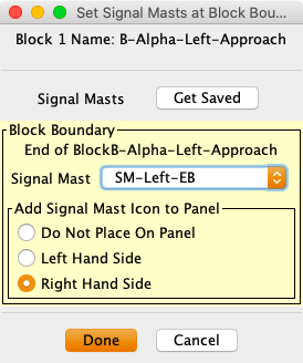
The dialog can also be used to remove masts. Set the signal mast selection to the blank row at the top of the list.
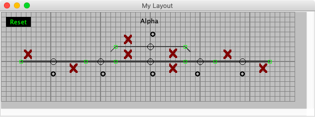
The new masts on the panel will display a red X. This occurs because there is no logic to determine the proper aspect.
In order to display an aspect, the signal mast needs to have logic to determine the proper aspect based on some set of rules. This can be done using Logix, scripting or Signal Mast Logic (SML). SML will be used for this exercise.
The Signal System definitions referred to earlier include the rules for setting signal mast aspects.
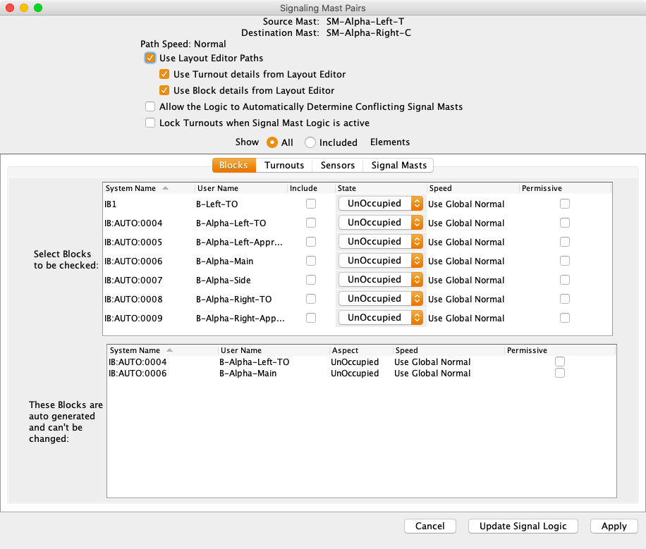
SML is based on signal mast pairs. From any signal mast it is possible to reach one or more signal masts depending on turnout positions. For example, the two head mast, SM-Alpha-Left-T, at the throat of Alpha Left, can reach either SM-Alpha-Right-C or SM-Alpha-Right-D depending on the position of T-Alpha-Left. This then defines the blocks that need to be unoccupied for the SM-Alpha-Left-T to display an aspect other than Stop. The actual aspect will depend on the current aspect for the destination mast and whether the route is normal or diverging.
Note: The signal mast at an end bumper does not have a destination mast and therefore will not have any logic.
Signal mast logic is maintained at PanelPro Tools ⇒ Tables ⇒ Signals ⇒ Signal Mast Logic.
While it is possible to use the Add button to create each set of signal mast logic, use the Tools ⇒ Auto Generate Signaling Pairs menu item. This will discover all the signal mast pairs and build the signal mast logic definitions.
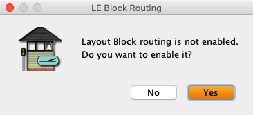
The first time SML is created, a system setting needs to be updated. Click on Yes.
A confirmation dialog will be displayed. Do not select Generate Sections. Click on Yes.
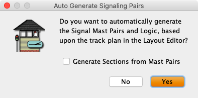
When the auto generate it done, the signal mast logic table will be shown.
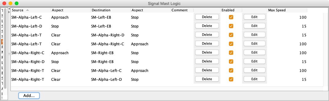
The panel icons now show proper aspects.
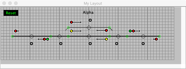
Click on the turnouts and occupancy sensors to verify that the signal mast logic is updating the aspects as shown by the icons changing.
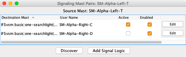
To see the detail for a specific mast, select Edit Logic from the entry in Signal Mast table or select Edit from the Signal Mast Logic table or select Signal Mast Logic in the right click context menu for the mast icon. Yes, those are 3 different ways to get to the same place.
Depending on the selection method, a summary will be displayed which shows the destinations for the signal mast and the active destination if there is one.
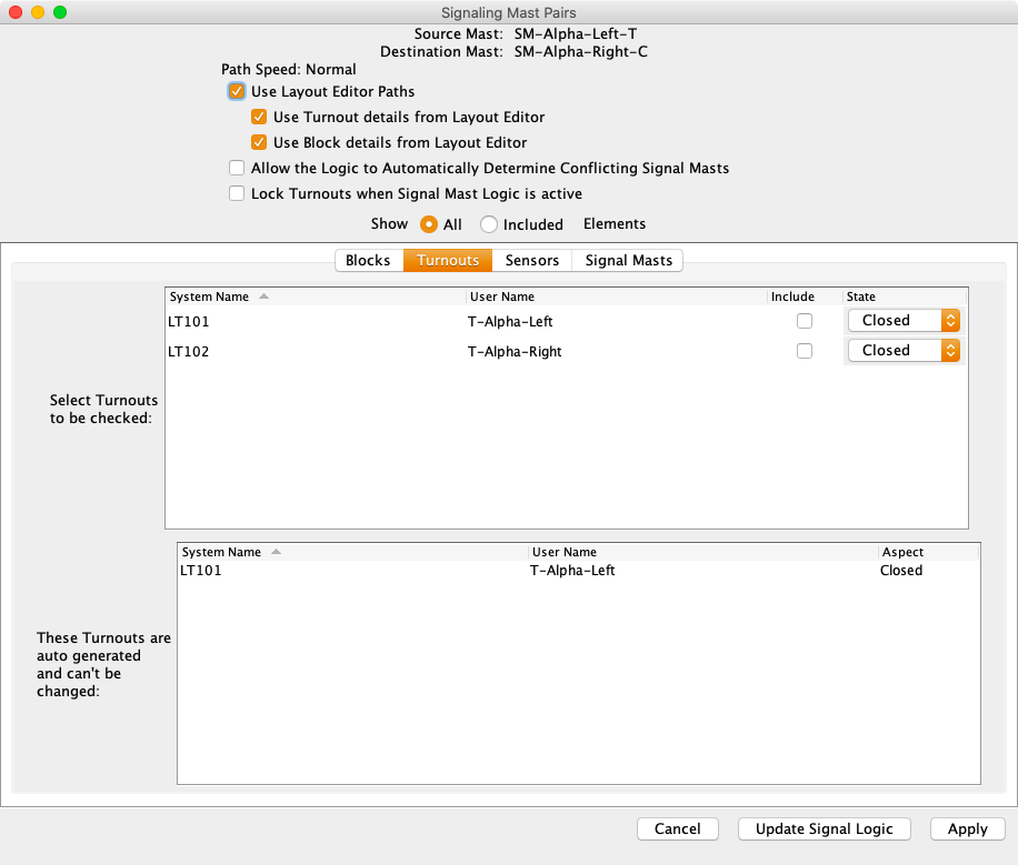
The next two images show the Block and Turnout tabs for the SML. The automatic sections were generated by the discovery process. The manual sections can be used to override automatic entries or add additional entries. If use Layout Editor Paths is turned off, then manual logic can be created. This might be needed for special cases.
The panel is now fully functional and can be used as the basis for other activities such as CTC, Entry/Exit or Dispatching.
Demo panel: GS-4-Masts SML.xml