Note: The PanelPro main menu has changed. See Loading and Storing Your Work for details. The menu references below are for the new menu structure with the old menu paths in braces.
The JMRI libraries contain the PanelPro application for creating panels to control or follow your (virtual) model railroad. This page introduces the application, and how to use it.
The PanelPro main menu provides access to the PanelPro components.
Some tools, such as Operations, have an option to add additional items to the main PanelPro menu.
PanelPro provides four separate ways to create Panels:
All Panel Editors use the same information about your layout stored in JMRI but each serves a different goal and approach.
The Panel Editor and the Control
Panel Editor let you build purely graphical (image based) Panels.
You can have as many Panels as you like, covering as much or as little of your railway as you
like, with overlaps in area or functionality if required. Panels might be diagrams showing
the state of the track and signals, or they might be prototypical signaling and dispatcher
panels. Or anything else you find useful to control your railroad; you have total flexibility
over their appearance. There are several standard graphics sets distributed with JMRI, but it
is often necessary to make some of the elements in an external graphics package to be
imported as PNG files. These might include the Panel Background, or the icons to attach to
active elements (switches, levers, track state, signals, etc.) which are then placed on the
Panel.
The Layout Editor builds a "Layout" which is a
logical description of your layout. A Layout, built with the Layout Editor, can be
used for directly controlling elements such as Turnouts and Signals; indeed many users find
it very suitable for this task. But, it is primarily designed for automation and
semi-automation within JMRI. For example, you can use the Layout Editor to construct a
description of your track and its blocks and signals. The software can automatically work out
how to set your signals based on the position of turnouts and whether blocks are occupied,
and the rules appropriate to your railroad (ie. select the signal rules based on different
company practices!, and no need to know how to create the rules to link your signals to the
state of turnouts, blocks and other signals !). Layout Editor Panels may also be used to set
up automatic running of trains on your layout using Dispatcher. In addition, the
Layout description of your railway can be used by scripts such as the included AutoDispatcher2 to automatically control your
trains. There are many other tools within JMRI which require a description of your railroad
and the description comes from the Layout built in the Layout Editor. The Layout Editor has
many rules built into it about how track is connected, the naming of blocks, etc. In order to
function, there are constraints on the appearance of track elements and how they are
used.
You can have multiple Layout panels, but you have to tell the software how to connect track
elements across the boundaries between multiple Layout panels.
The Switchboard Editor is easier to set up, using a simple grid of pre-defined buttons or indicators. It is limited to the basic inputs (Sensors) and Outputs (Turnouts and Lights) and has a couple of ready-made graphic display styles.
 Many people use a combination of panel types, with the
Layout Editor creating schematic panels to handle the actual configuration for signals and
Panel Editor providing exactly the appearance desired.
Many people use a combination of panel types, with the
Layout Editor creating schematic panels to handle the actual configuration for signals and
Panel Editor providing exactly the appearance desired.
Clicking on a Turnout symbol on any of the Panels flips it from Closed to Thrown and
vice-versa (unless operation is disabled in the Configuration). A Turnout also has "Unknown"
and "Inconsistent" states, represented by an icon with a "?" and "X" respectively. These
represent a state where no information has been received, and where the information is
internally inconsistent (e.g. both Closed and Thrown at the same time).
Control of items like Turnouts from a Panel can be done in various ways. For example in Panel
Editor, you could have a turnout icon covering a turnout on a schematic diagram. When you
click on it, the turnout on the layout would be commanded to change, and the track diagram
would show which way a train would be routed. Or you could use icons that show a lever to the
right or left, and create a panel that looks like a traditional US&S panel.
"Sensors" can be used to represent occupancy indicators or other inputs. The default icon is a small circle, with color used to represent the state of the sensor. These respond to changes on the layout automatically. Clicking on a sensor causes the sensor to alternate between "Active" and "Inactive" states. With the default icons, Active is a green circle and Inactive is an empty circle. These are meant to represent a lit/dark panel indicator. A red circle represents the "unknown" state, used when no information has yet been received from the layout.
JMRI Panels are made using one of the Editors. Start the Editor by selecting "New Panel..." then "Xxx Editor" from the "Panels" menu on the main window.
After getting the Panel the way you want, you use the Store ALL table content and
panels... {Old: Store Panels...} entry in the
File {Old: Panels} menu to write it to an .xml
file on disk, allowing you to reload it the next time you run JMRI and see all your turnouts,
sensors etc as you configured them.
A PanelPro xml data file contains ALL of the tables and panels. It is recommended to start
with just one panel/configuration file for your layout. Except for some specific use cases,
multiple xml files create confusion and errors.
Think of the xml file as a book. There are chapters for turnouts, sensors, signals, blocks, Logix, etc. Each panel is also a chapter. As the layout design is progressing, various chapters are created and modified. It is a good idea to periodically save the changes. Some people use an incrementing file naming approach. Others rely on the backupPanels directory where you can find older versions of the configuration file (see the JMRI Configuration Files)
When starting your next PanelPro session, either load the latest xml file via the File ⇒ Load table content and panels... {Old: Panels ⇒ Open Panel...} menu item or add an "Load table content and panels..." entry to "Preferences > Start Up" to do it for you.
With the Panel Editor, you can make a control panel look and operate any way you want because they are icon-based. For example, instead of using track-schematic icons for turnouts, you could use small images of the levers and plates on CTC machine. This would give you "mechanical" levers you can flip back and forth with a click. This can be made absolutely prototypical, or can be simplified for easier and faster operation, as you prefer.
A panel is one or more background pictures, on which are drawn icons to represent Turnouts, Sensors and Signals on the layout. You can build the background from small icons (as in the image above left), or provide a detailed drawing that you created in a drawing program (image above right).
You can use these tools to configure quite complicated panels for even large layouts. The example above is from Nick Kulp's Cornwall Railroad. There's a page on the main web site that describes this in detail. Robert Bucklew's Quaker Valley Lines is also building a CTC panel using PanelPro.
For more information about Panels created using Panel Editor see the Panel Editor help page.
Control Panel Editor is simply an alternative view and controller with the same content data as Panel Editor. Control Panel Editor allows you to edit a Panel using menus instead of a separate editing window.
It's also possible to create a Control Panel where the "track" lines change color to indicate whether the block is occupied. Control Panel Editor supports using Warrants and automatic running of trains.
For more information, see the Control Panel Editor help page.
 The Layout Editor helps you create
simple schematic panels, while simultaneously setting up the block and signal logic needed to
operate the layout. Its strength is its ability to capture how the tracks are connected,
where each block is located and how each signal is related to blocks. On the other hand, it
limits by design the ability to customize how the panel appears. For example, you can only
place one Turnout symbol with the same User Name.
The Layout Editor helps you create
simple schematic panels, while simultaneously setting up the block and signal logic needed to
operate the layout. Its strength is its ability to capture how the tracks are connected,
where each block is located and how each signal is related to blocks. On the other hand, it
limits by design the ability to customize how the panel appears. For example, you can only
place one Turnout symbol with the same User Name.
 In Layout Editor you edit
your Panel by activating the "Edit Mode", which makes the connections between elements and
the layout visible (See figure to the right, notice the small circles). For example, you can
click on the circle in the middle of a track segment and select the associated occupancy
detector (Sensor) on the layout. Once you've done that, the color of the track segment on the
screen will change when the track is occupied. You can configure the colors used, the width
of the track lines, and other details of the presentation.
In Layout Editor you edit
your Panel by activating the "Edit Mode", which makes the connections between elements and
the layout visible (See figure to the right, notice the small circles). For example, you can
click on the circle in the middle of a track segment and select the associated occupancy
detector (Sensor) on the layout. Once you've done that, the color of the track segment on the
screen will change when the track is occupied. You can configure the colors used, the width
of the track lines, and other details of the presentation.
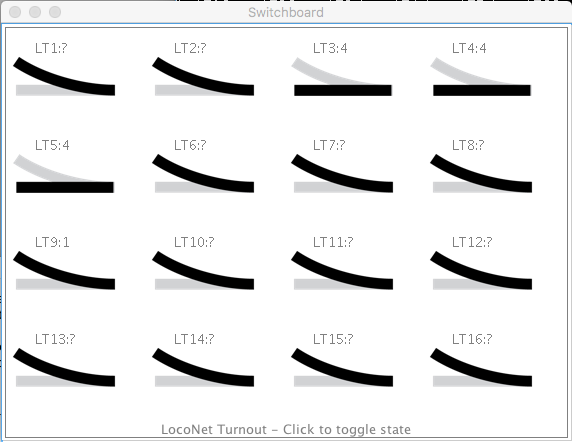
Switchboards provide a visual control grid for your JMRI layout "out of the box".
To create a new Switchboard, from the Panels menu, choose New Panel > Switchboard
Editor.
For more information, please see the Switchboard Editor help page.
PanelPro can communicate with more than one layout control system. For example, the Cornwall Railroad mentioned above uses C/MRI hardware for sensing the status of blocks and turnouts on the layout, but drives turnout positions through a Digitrax DCC system.
To configure the program to talk to multiple systems, add both in JMRI Preferences using the + tab on the Connections pane. For more information, see the Preferences panel Help page.
If you add a Turnout, Sensor or Signal Mast to a Panel using just a number, e.g. "23" in the Add... pane of a table, its System Name will be created using the System Connection Prefix as set in the Preferences panel -> Connections tab (e.g. LT1 for a turnout on the L LocoNet connection). As a second system connection is required to use a different prefix, it is simple to use more than one hardware system at the same time. See the page on Names & Naming for more information.