Logix™ provide a powerful capability for JMRI to monitor one or more conditions on a layout, and take action when these conditions change in a user-specified way. Logix can be used to control signals, crossing gates, and other types of automation on the layout. The user interface is designed to be user friendly to all users with basic familiarity with JMRI. A Logix provides a means for setting up user-specified logic in an intuitive manner, without the user having to be familiar with mathematical logic.
The documentation below describes Logix, and discusses how to set them up. The documentation is divided into sections; click below for easy access to a listed section. If you prefer to try before reading much, read Introduction to Logix and Conditionals, then click Getting Started and follow those instructions. Return here to read about what you did.
Detail State Variable and Action Lists:
Notice: The examples described in this document use the traditional Conditional List editor.
Conditional Editor details:
Logical listing of all Logix documentation pages
A Logix is a small group of Conditionals focused on a single task on the layout. Each Conditional may be viewed as a statement of the form:
if (logical expression) then (action)
The "logical expression" part of a Conditional tests the state of a group of user-specified conditions on the layout, for example, whether certain turnouts are closed or thrown, or whether a block is occupied. The "action" part of the Conditional specifies what action is to be taken if the state of the logical expression changes.
For example, one Logix with several Conditionals could control the appearance of one signal head. The first Conditional could check conditions for a GREEN appearance. A second Conditional could check on another allowed appearance. Other Conditionals could check for other appearances. A Logix is flexible enough so that the signal rules of any railroad might be set up, provided, of course, information needed to test the required conditions is available. So with only one Logix, a user should be able to set up the required logic for setting the appearance of one signal head.
Think of a Logix as a small group of one or more Conditionals that address a single need. Being able to group all the Conditionals that address that single need in one Logix simplifies things. Only one System Name is needed for all the logic addressing the task, and grouping all the logic for the task in one place, makes it much easier to see how related logical expressions might work together and how they might affect each other.
Except when it is being created or edited, a Logix is "active", which means that the entities (turnouts, sensors, lights, etc.) in logical expressions of the Logix's Conditionals are being monitored. Whenever the state of any of the monitored entities of a Conditional changes, that Conditional "calculates" its logical expression. If the result of the calculation changes the value of the logical expression, then the specified actions of the Conditional are taken.
The monitored entities specified in the logical expression of a Conditional are called "State Variables" and the result of the calculation is the state of the Conditional. It is the change of state of the Conditional that causes it to issue commands for its actions to occur. The logical expression is also referred to as the "antecedent" of the Conditional and the group of actions to take is also called the "consequent" of the Conditional.
A Logix does not have a state as many JMRI entities do. A Logix does have the capability of being "enabled" or "disabled", however. When a Logix is disabled (not enabled), the logical expressions of its Conditionals are still evaluated, but the actions specified in the Conditionals are not taken. Whether each Logix is enabled or disabled is saved when the Logix is saved to disk, so a Logix that was disabled when last stored will start up disabled when next loaded from the configuration file. When a Logix that has been disabled is enabled, the states of all its Conditionals are set to UNKNOWN, and all Conditionals are calculated.
A Logix is defined via the Logix Table that can be accessed by selecting Logix Table in the Tools menu. The Logix Table lists all currently defined Logix by their System Name and User Name. The table also shows whether a Logix is "Enabled". The last column of the table provides an easy way to edit a Logix and its Conditionals. Clicking the Select choice box for a Logix, will drop down a menu with four choices; Edit, Browse, Copy and Delete. Each choice will bring up a pane for the corresponding operation.
To create a new Logix, click the Add... button at the bottom of the Logix Table pane. This will bring up a Create Logix window. Entering a System Name and a User Name, then clicking Create Logix, will create the Logix, and bring up the Edit Logix window. This window allows Conditionals to be created and edited. Once a Logix is created, its System Name cannot be changed. Its User Name, however, may be changed in either the Logix Table or the Edit Logix window. A new User Name may be any useful text, provided the new User Name was not previously assigned to another Logix.
A Logix is named using the JMRI convention. The System Name for the Logix always must begin with the two letters IX and is usually followed by a number selected by the user. For example, valid Logix System Names include: IX1, IX34, and IX100. The user name is whatever the user wants to use to identify the particular Logix, for example, "Signal 5 Control". As a convenience to the user, if the entered System Name does not begin with IX, the program will add IX in front of what is entered. For example, to enter a System Name of IX32, simply enter 32 in the System Name field, and the program will do the rest.
The Edit Logix window displays the System Name and User Name of the Logix at the top. The User Name may be changed by entering/modifying the text in the User Name field. Next is a table of Conditionals belonging to the Logix. To add a new Conditional, click the New Conditional button under the Conditional Table. This will create a new Conditional and open the Edit Conditional window allowing the logical expression and actions of the new Conditional to be defined. An existing Conditional may be edited by clicking the Edit button of that Conditional in the table. The User Name of the Conditional may be changed in the table. The User Name of a Conditional may be any useful text, provided it is not the same as the User Name of another Conditional in the same Logix. The User Name may be the same as the User Name of a Conditional in another Logix. When editing the User Name (or any item in any JMRI table) please remember to move to another cell in the table so that the program is notified that you have finished your entry, otherwise the entry may not take effect.
Clicking Calculate under the Conditional Table causes all Conditionals of the Logix to be calculated. Resulting states are displayed in the State column of the table. However, since the Logix is being edited it is inactive and therefore no Conditional actions are taken. When the editing of the Logix is done, the Logix is activated and may be enabled to allow Conditionals to execute their actions.
The order of Conditionals in the Conditional Table may be changed by clicking Reorder (below the Conditional Table). Clicking Reorder changes all edit buttons in the last Column of the table to First. Select the Conditional that is to be first, and it is immediately moved to the top of the table. All remaining buttons change to Next. Select remaining Conditionals in desired order, until all buttons change back to Edit.
The only time when the Conditionals are evaluated in the order listed is when all of their states are UNKNOWN, such as when the Logix is being enabled. Conditionals are evaluated when one of their state variables changes its state. If an entity is used as a state variable in more than one conditional, it is indeterminate which conditional is evaluated first.
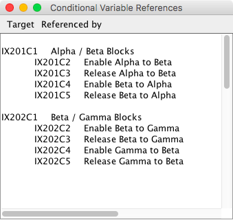
When Done is clicked at the bottom of the Edit Logix window, any change in the Logix User Name is checked and made. A check is made for inconsistencies in specifying that an entity (sensor, turnout, etc.) referenced in multiple state variables is not monitored as a trigger for calculation of the Logix, and a warning message appears if any inconsistencies are found. Then the Logix is activated, the Edit Logix window is dismissed, and the user is returned to the Logix Table. Immediately before the Logix is activated, the state of all its Conditionals is set to UNKNOWN. Immediately after activation, all Conditionals are calculated.
The Edit Logix window also provides a way to delete a Logix if it is no longer needed. Click Delete Logix to delete the Logix being edited and all its Conditionals. This operation can also be done by selecting the Delete item from the drop down Select menu on the Logix Table.
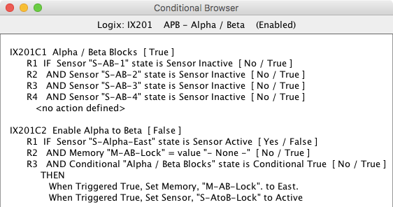
Selecting the Browse item from the drop down menu on the Logix Table will open a window with a list showing the details for each conditional. It is an effective way to review the entire contents of a Logix. Click on the close button to close the window.since 4.7.3
Selecting the Copy item from the drop down select menu on the Logix Table will show a series of dialog windows that provide a way to copy the Logix and any or all of its Conditional to a new or existing Logix.
A Conditional's System Name has the form IXnnnnCmm, and is set automatically when the Conditional is created by the user clicking New Conditional in the Edit Logix window. The System Name of the first Conditional for Logix IXnnn will always be IXnnnC1, the second Conditional will have System Name IXnnnC2, and so on. The User Name of a Conditional is whatever the user wants to assign to identify the use of the Conditional. An entered User Name must not be used by more than one Conditional within a given Logix, however. The System Name and User Name are displayed at the top of the Edit Conditional window. The User Name may be entered/edited there or in the Conditional Table of the Edit Logix window. The User Name of a Conditional may be any useful text, provided it is not the same as the User Name of another Conditional in the same Logix. The user name may be the same as the User Name of a Conditional in another Logix.
As mentioned above, Conditionals are statements of the form:
if (antecedent) then (consequent).
Therefore a Conditional has two distinct parts: its "logical expression" and its "actions". These are discussed separately below.
Logical expressions connect the states (true or false) of "state variables". State variables test conditions on the layout or in the program, for example, if a sensor is active or inactive, if a turnout is closed, if a signal head is red, if the fast clock time is between 10:00 and 11:00, etc. State variables are linked together in a logical expression by logic operators. For a list of currently available state variables, see State Variables
Logic operators currently available are NOT, AND, AND NOT, OR and OR NOT. The AND operator is set up automatically by the program. For each state variable, the user selects whether the NOT operator is to precede the state variable. If the NOT operator precedes the state variable, the true/false value of the state variable is reversed. For example, if "Sensor Active CS5" is true, "NOT Sensor Active CS5" will be false, and vice versa. Note that "Sensor Active CS5" is sometimes not the same as "NOT Sensor Inactive CS5", because Sensor CS5 may be in the UNKNOWN state.
Logical expressions read like written statements. It is easy to set up a logical expression to evaluate many situations on the layout. For example, "if block 10 and block 11 are occupied and turnout 20 is thrown" would be set up as:
Sensor "LS1020" is Sensor Active AND Sensor "LS1021" is Sensor Active AND Turnout
        "LT20" is Turnout Thrown
where LS1020 is a sensor that is true when block 10 is occupied (perhaps from a BDL168), sensor LS1021 is true when block 11 is occupied, and Turnout Thrown LT20 is true when turnout LT20 is thrown. This logical expression would calculate to true if all three of the state variables are true, i.e., if block 10 is occupied AND block 11 is occupied AND turnout 20 is thrown; otherwise it would calculate false.
Actions may be specified for each Conditional. A number of action types are available. For example, Set Turnout, Set Signal Appearance, Trigger Route, etc. For a list of currently available action types, see Actions. Each action has a user selectable option of being performed if: 1) the logical expression changes to true, 2) the logical expression changes to false, or 3) the logical expression changes. This means a conditional may actually be three statements.
Note that the state of any antecedent is considered to have changed when a Logix is first enabled. This means that any "do on change" actions will be executed when a Logix is first enabled, including those that are enabled when JMRI is started
The Edit Conditional window is where logical expressions are set up and where actions are specified. The Edit Conditional window is displayed when a Conditional is created, or when the Edit button of a Conditional is pressed in the Edit Logix window. The Edit Conditional window displays the System Name and User Name of the Conditional at the top. The User Name may be edited by entering/modifying the text in the User Name field. Any text may be used, provided it doesn't duplicate the user name of another Conditional in the same Logix. Next are two sections--one for the setup of a logical expression and one for set up of the actions.
The logical expression section contains a table of state variables, with two buttons and a drop down menu box below. The drop down menu allows the choice of what logical operators to use in the antecedent. The choices are: all AND's, all OR's or Mixed. Mixed allows the user to specify any combination of AND's, OR's and NOT's. When this choice is made the logical expression requires parentheses in order to be unambiguous. So, when this choice is made, a text field is displayed so that parentheses can be inserted and the expression modified. The state variables are represented in the expression by their row number.
The first column in the state variable table is the row number of the variable. The next column displays the logic operation preceding the variable in the expression. In the case of "Mixed" a choice box allows the user to choose an operation. However these choices can be changed in the antecedent text field and it is the text field expression that the Conditional uses to determine its state. The third column contains a choice box that allows the user to select the NOT operator as needed.
The fourth column is a description of state variable and the condition to be monitored to be for its state to be true. The next column shows the state that was last tested for the variable (true or false). The state displayed includes the effect of the NOT operator, if NOT is selected.
The "Trigger" column sets whether the state variable should cause the Conditional to perform its actions when this variable changes. Note that the current states of all the variables are always used in the calculation of the Conditional's state. The "Trigger" setting allows a state variable to be "passive" and not cause the conditional to evaluate its state. That is, such a variable state is a necessary condition, but not a sufficient one to cause any actions to take place.
Note: Disabling state variable triggers should be done with caution. Actions are performed only when the state of the logical expression changes. Disabling a trigger can prevent actions from be executed even when this state has changed.
Next is a column of Edit button to modify an existing state variable. The last column of the table (Delete buttons) is used to delete a state variable if you decide it is no longer needed.
Press the Add State Variable to add a state variable (a row in the State Variable table). This brings up a window with a choice box for the user to select a state variable type. Available state variables are documented at State Variables. When a type is chosen the Edit Variable window displays a text field for the name of the entity to be used for the state variable. When a name (either System Name or user name) is entered, it must correspond to an existing entity (sensor, turnout, light, etc.). Depending on your selection method, a tabbed Pick List, a single Pick List or a dropdown combo box will be displayed to aid in name selection.
At any time during the entry of state variable data, the Check State Variables button may be clicked to check the entered data and evaluate the state variables. When this button is pressed, the checking and evaluation proceeds until the check completes successfully, or an error is detected. If an error is detected, the checking stops for the user to correct the error and click Check State Variables again. Please remember after editing the System Name and data items to click a different cell in the table before clicking Check State Variables (or Update Conditional at the bottom of the window) so that the program is notified that you have finished your entry. Otherwise your entry may not take effect, and an error may be reported unnecessarily.
There are two policies that can be taken after a conditional's state is evaluated:
Which policy to use is chosen by the radio buttons in the middle of the Edit Conditional window. The Execute actions on change of state only button prevents unwanted behavior from occurring when multiple instances of the "on true" or "on false" actions are executed. That is, if successive triggers cause the logical expression to be evaluated to the same state, only the first trigger will execute the actions. Normally, it is best for a conditional to execute its actions only when the state of the conditional changes. However, if it is important to maintain the actions associated with a particular state of the Conditional the Execute actions whenever triggered button should be used. If external events undo some of the actions of the conditional but do not change the state of the conditional, then this policy will execute the action on any trigger.
The Actions section of the Edit Conditional window contains a table of actions, with two buttons below for adding a new action and reordering the list of actions. The section provides for specifying the actions to be taken when a Conditional is calculated and changes its state. The action table consists of a column for the description of the action to be taken and two columns of buttons, Edit and Delete, for editing or deleting an existing action. To add a new action, press the "Add Action" button. A new "Edit Action" window will appear. Select an action type in the type box, and data items needed to completely specify the action will appear to the right of the type box. When a name must be entered, the name must correspond to the System Name or the User Name of an existing entity (sensor, turnout, signal head, etc.) of the proper type. Depending on your selection method, a tabbed Pick List, a single Pick List or a dropdown combo box will be displayed to aid in name selection. Available action types are described in detail at Actions. If you use User Names to specify your actions, the same caution noted above applies. Be very careful when editing User Names that are used to specify actions.
For each action, three options are available for when to perform the action: 1) On Change to True, 2) On Change to False, and 3) On Change. These refer to the calculated state of the Conditional, which is equal to the value of the logical expression as specified in the state variable table. One of these options must be selected. When done, click either "Update" to install your changes, "Cancel" to close the window without any changes or "Delete" to remove the action entirely.
To change the order order of the Conditionals in a Logix, or the order of the actions in a conditional click the "Reorder" button. The right-most buttons in the table will then let you select the first one, next one, etc. Note however, this is merely the order in which the commands are issued but do not guarantee that their final effect will occur in the same order. If it is necessary to have actions take place in a specified order, use separate Conditionals for each action and chain the Conditionals such that a preceding action's completed state is the state variable for the succeeding action.
When the logical expression and actions have been specified, click Update Conditional at the bottom of the window. This initiates a check of the logical expression (the same as done by Check State Variables) and a check of entered data for actions. If the Conditional's User Name has been edited, it is also checked. If an error is found, a message box opens announcing the error, and the update is stopped to allow the user to correct the error and click Update Conditional again. If no error is found, the Conditional is updated with the entered data, the Edit Conditional window is closed, and the user is returned to the Edit Logix window.
Two other buttons are available at the bottom of the Edit Conditional window. Clicking Cancel will close the Edit Conditional window without updating the Conditional. Clicking Cancel results in loss of any data that has been entered. The other button, Delete Conditional, provides an easy way to delete an unneeded Conditional. Click Delete Conditional to delete the Conditional being edited and return to the Edit Logix window.
The following steps let you create your first Logix and become familiar with how the Logix user interface works.
You'll have created a Logix to control the setting of a turnout according to the states of two sensors. It's as simple as that. It took you more time to read this tutorial than to create the Logix.
Logix are kept in your layout configuration, along with Turnouts, Sensors, Signal Heads, control panel setup etc. To store this information on disk, allowing you to reload it next time you run JMRI, see Loading and Storing Your Work.
Note that the enabled/disabled state of each Logix is saved in the configuration file.
This section contains questions and answers that normally are not needed by Logix users, but in some cases were important or of interest for previous versions of Logix.
Why have a "group" of Conditionals instead of just single Conditionals?
A group of Conditionals was chosen for several reasons, including:
How is a Logix started?
Start of a Logix is similar to the way a light, a route, or other continuously running JMRI entity starts. Internally a Logix has an "activate" method, that is called when the Logix is created, after it is edited, or when it is loaded from a configuration file. This method starts listeners for items in the state variables of the Logix's Conditionals. When any of these listeners fires (indicating that the watched property of a state variable has changed), the Logix is calculated, resulting in appropriate actions being taken, provided the Logix is enabled.
What is the initial state of a Logix and its Conditionals?
When a Logix is created or edited, the initial state of each Conditional is true or false as shown in the Edit Logix window. When a Logix is loaded from a configuration file, the initial state of each Conditional is UNKNOWN.
A Logix is enabled automatically when it is created. A Logix may be disabled/enabled by unchecking/checking the button in the Enable column in the Logix table. For example, you might want to disable a Logix while you're creating and debugging it, until you're certain that you have it set up properly. A Logix may be enabled or disabled dynamically by another Logix (see allowed Actions. ).
When JMRI stores the layout configuration in a file, e.g. a panel file, all Logix information, including the enabled/disabled state of the Logix, is stored. When a Logix is loaded from a configuration file, its enabled or disabled status is set according to what was saved in the configuration file. This is done so that people can disable their Logix while debugging them, yet still save and restore the configuration as needed.
This is a complex question that depends upon many things, such as, how the user has set up for turnout feedback, block detection, etc. When a configuration file is read, the various entities (sensors, turnouts, signal heads, etc.) are loaded in an almost random order. So it's not reasonable, for example, to calculate each Logix as it is loaded, since the needed state variable entities might not be present when the Logix is loaded. And, since most entities will load in UNKNOWN state, calculating a Logix immediately after the entire configuration file is loaded doesn't produce a clean start up either. So when a Logix is loaded, the state of each Conditional starts as UNKNOWN. Immediately after the entire configuration file is loaded, all Logix are activated, and then all the Logix are calculated. The state of Conditionals changes from UNKNOWN to true or false. But will the calculated state of the Conditional be "correct" if one or more of the state variables is evaluated from an entity in an UNKNOWN state? For example, think of a turnout in an UNKNOWN state--Turnout Thrown and Turnout Closed will both evaluate to false. As listeners continue to fire for state variables, eventually every entity has its correct current state and the Logix will work fine. You can monitor this action by watching states in the Sensor Table, the Turnout Table, etc. Conditions at start up certainly are something to keep in mind when setting up a Logix.
Normally Triggers Calculation should be checked in all state variables, so a change in any of its state variable will trigger calculation of a Logix. This results in the Logix quickly reacting to changes on the layout, and maintaining the status of signals, turnouts, etc. as desired. There are situations, however, where it is desirable to test the state of an entity, but not use it as a calculation trigger. The following paragraphs describe a couple of those situations, but there are others.
Occasionally a "logic loop" can result if triggering is not suppressed. For example, if the state of a turnout is tested in a state variable, and the same turnout is set in an action of the same or another Conditional of the same Logix, continuous triggering (a logic loop) could result. The easiest way out of this dilemma is to test the turnout, without using it as a triggering entity. This is done by unchecking Triggers Calculation in all state variables where the turnout is specified. If the turnout is used in state variables of more than one Conditional of the Logix, it must be unchecked everywhere it is used to suppress using it as a trigger.
Another situation arises when Delayed Set Sensor action is used with an internal sensor to trigger a second Logix after the delay time has elapsed. If the second Logix is not to be triggered before the delay time elapses, all of its state variables, except for the delayed internal sensor, should be unchecked. This scenario might occur, for example, if a Conditional turns on something as its first action, and sets a Delayed Set Sensor as its second action to turn off that something after a specified time provided certain conditions are met.
A "logic loop" results when the program appears to slow down significantly or lock up as multiple Logixs are continuously triggered by changing references to each other. The best way to avoid a "logic loop" is to be aware of situations that can lead to a loop, and plan your logic to avoid such situations.
A "logic loop" can result within a single Logix when a state variable (sensor, turnout, etc.) that triggers the Logix is also changed by that same Logix. The Logix editor will detect some situations that could result in a loop, and will issue a warning when you close the Logix. Heed these warnings! A warning doesn't mean that a loop definitely will result if you continue. The warning message is a "wake up call" that you should study carefully what you're doing to make sure a loop won't result.
A more complicated situation involving two or more Logixs can also result in a "logic loop". For example, if Logix 1 is triggered by sensor A, and has an action that changes turnout B, and Logix 2 is triggered by turnout B and changes sensor A, the potential for a loop exists as these Logixs trigger each other. You can easily extend this idea to triggering chains (loops) involving three or more Logixs, and even to interactions between Logixs and Routes. There is no test in the program to warn about loops involving multiple Logixs. (To develop such a test would be very difficult.)
When they do occur, "logic loops" can be a bit scary to trouble shoot. Your computer may appear to be locked up, or slowed to a crawl as the loop uses up most of the available computer time. Fortunately JMRI provides tools to help in design and debugging. Unchecking "Triggers Calculation" for a state variable (discussed above), can help you design around loops when you have identified the Logix causing the looping problem. To get around the lock up or slow down problem, start with all your Logixs disabled, (see below) then enable them one by one until you discover the loop.
If the panel file containing Logixs loads automatically when the program starts up, press F8 as soon as you see the small JMRI splash screen (the first thing you see during start up). Your panel file will be loaded with all Logixs disabled.
If you load your panel file manually using the File ⇒ Load table content and panels... menu, before loading your file, go to the Debug menu and select Load Logixs Disabled. After responding OK to the message, load your panel file as you normally would. Your panel file will be loaded with all Logixs disabled.
After loading your panel file, open the Logix Table and verify that all Logixs are disabled. If you know which Logix is causing the trouble, you can then fix it or delete it, re-enable the other Logixs, and save your panel file. If you don't know which Logix is causing the problem, you can enable your Logixs, one by one, until the loop occurs. When the loop starts, you know that the last Logix you enabled is at least partly responsible for the problem. At this point you should restart the program with all Logixs disabled, and fix or delete the Logix you identified.
CAUTION: It's wise to save your panel file frequently when entering Logixs. If a logic loop occurs, it may be difficult, if not impossible, to save your panel file before shutting down the program. Remember that a Logix is activated as soon as you click Done in the Edit Logix window. Also, remember that hitting an Edit button in the Logix Table deactivates the selected Logix before opening it for editing, offering a possible way to break into a logic loop without restarting the program.
Logix documentation is divided into eight different help pages. While these are referenced via links in various places, not all are easy to find (perhaps three links down). They are additionally listed here for convenience.