This page describes how PanelPro is used to control Otis McGee's SP Shasta Route layout.
The SP Shasta Route layout is a model of the Southern Pacific's Shasta Division, Black Butte Subdivision in 1952. There's an extensive website describing it.

Otis's main goal is operations with prototypical fidelity. In 1952, the prototype was a mix of CTC signaling on the lower (western) half of this division, and timetable-and-train-order on the upper (eastern) half. The layout is meant to reproduce this as closely as possible.
Eventually, Otis wanted to reproduce the dispatcher's experience with an operating CTC machine. In 1952, a large CTC machine was installed at the Dunsmuir station, part of the modelled portion of the railroad (see prototype photo to the right). Otis was not interested in computer-based control panels, even as a temporary measure.
The first project was to introduce ABS signaling. This would let us install and operate signals on the layout, and use them for collision avoidance during the initial operating sessions.

After some research, Otis decided to use C/MRI for layout control, and NCE DCC to operate the trains. C/MRI was well suited because the layout is large, but there are a large number of control points (inputs and outputs) needed at specific points like the CTC machine, staging and operational yards, etc. The C/MRI SUSIC and SMINI units were well suited in size to these I/O requirements.
All turnouts on the layout are operated by Tortoise slow-motion switch motors, operated through C/MRI Switch Motor Controller (SMC) boards and slide switches on the facia (this method was originally perfected on Rick Fortin's Sierra Western & Santa Fe Railroad.) Locally operated turnouts have the slide switch directly connected to the SMC board, operating the turnout without going through the computer.

Mainline turnouts are controlled through PanelPro, because it needs to know their position for operating the signals, and because once the CTC machine is installed, the turnouts will be controlled from both the fascia and the CTC machine. To do this, the toggle switch is connected to a C/MRI input, and the SMC is connected to a C/MRI output. A JMRI Route is then used to operate the turnout when the slide switch changes.
This works very well when the program is running, but does an unfortunate thing when the C/MRI system is first turned on. When power is first applied to the C/MRI system, before the computer has had a chance to initialize it, the outputs go to random states (the SP Shasta C/MRI system mostly has them inactive, but there are a couple that go active). This causes the switch machines to move to random locations, with no regard to the position set by the fascia slide switches. This can throw turnouts under parked trains, etc. To help this, we start PanelPro before powering up the C/MRI system, so that the program will rapidly set the outputs once the C/MRI turns on. Combined with the slow speed of the Tortoise machines, the turnouts only move a little way.
We're considering a more elegant situation, where power to the SMC boards is interrupted by a relay until the computer has been able to communicate enough with the C/MRI system to switch a specific output. Since the SMC machines won't have power, they won't be able to move the Tortoises until they are under positive control.
PanelPro legacy "Simple Signaling Logic" is used to operate each signal. Note that this is entirely "behind the scenes"; there's no control panel on the computer, and the dispatcher has no way to set the signals. Instead, they just respond to how turnouts are set and where trains are present, essentially just warning train engineers of unsafe conditions ahead.
Also during this stage, JMRI scripting was used to control a large turntable and roundhouse complex at the Dunsmuir yard. Since every locomotive on the layout is highly detailed and has sound, Otis wanted to turn off power to roundhouse tracks that are not currently aligned with the turntable. This greatly reduces the sound volume in the engine terminal, and makes it much harder to accidentally drive a locomotive into the turntable pit. A pair of scripts were used to watch the turnout operation, and turn on and off appropriate channels in C/MRI relay cards to control track power in the area. This is an interesting combination of DCC and C/MRI power control!
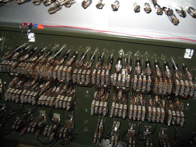
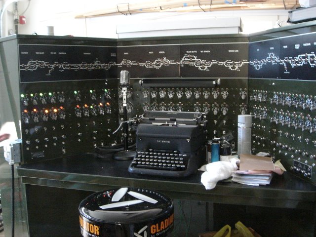
While the signaling phase was going on, Otis commissioned Rod Loder to build a CTC machine. Rod does excellent work, using prototypical techniques and original components to the greatest extent possible. The photo's below show Rod delivering it, the original switches and indicators on the back of the panel, the beginning of the roughly one thousand connections needed to the C/MRI system, and the final panel with the first few indicators lit.


PanelPro is providing USS signal logic to drive the panel, and this CTC panel is providing an excellent test-bed for that logic. They're evolving together.

Although we've not started on this yet, in the long run we'd like to have PanelPro provide assistance for the staging operations. The railroad has two loop staging yards, a single-ended yard, and a large double-track helix connecting the ends of the layout that also serves as staging. PanelPro is already operating the throats for these yards from physical control panels: When a button is pushed to select a particular track, the program aligns the throat turnouts and orients the power for entrance or exit in the loops. It also reads the track occupancy status and lights indicators on the panels to show which tracks are occupied. All of this is done with a total of about 48 JMRI Routes.
The next step, which we probably won't work on until after the CTC machine is completely operational, is to add controls so the computer can help with staging operations. The idea is that a train crew will bring their train to the appropriate end point, tell the local operator that they've finished their run, and then the operator will have the computer run the train into staging while the crew goes off to their next assignment. This removes the unprototypical part of staging from the crew's experience, without adding too much unprototypical workload to the operator.