Within JMRI there are a number of editors which can produce graphical representations for controlling a layout. In this tutorial, we are using the Layout Editor. The Layout Editor has the ability to construct a logical representation of your layout from the track diagram, so it will "know" which turnouts, track segments, blocks, etc.. are connected in which order. From this logical representation it can construct further rules for running your signals (and other aspects of your layout).
The other common editor is the "Panel Editor". This is excellent for constructing a graphical control panel, you are able to use any graphical arrangement. One typical use of the Panel Editor might be to construct a representation of a prototype signal/turnout control desk or lever frame. In practise, both the Layout Editor and the Panel Editor are used, the Layout Editor gives the logical representation and the Panel Editor produces graphically pleasing control panels for operating the layout.
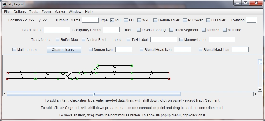
With the Layout Editor, begin by positioning the Turnouts and some Anchor Points for plain track. The Name of the Turnout (the User-Name defined in the Turnout Table) to be positioned is entered into the "Name" field before placing the Turnout on the Layout. The Bay Turnout is a "LH". Once placed, clicking on the element will change the turnout on the real layout. The cross over can be done with a single element, the "LH Xover". (The video shows how to attach the second turnout to the Cross-Over).
Note that Turnouts cannot directly connect to each other, but a small section of plain line has to be drawn from the anchor point squares on the two turnouts. Additional Anchor Points are placed for where the track needs to be joined, or where a block boundary might be required.
There is a special case of Anchor Point, called a Buffer Stop. This expects track from only one direction.
When Anchor Points have been fully connected to each other with Track Segments, they change colour from Red to Green.
There are Zoom Tools, an alignment grid and "snap to grid" options which will help to produce a tidy diagram. In the illustration below, some of the track segments have been declared as "MainLine" and thus are bold, with other segments being ordinary weight.
Having drawn the track diagram, the next step is to give track segments block names, and attach sensors to those blocks.
Select a track segment, and with the context menu (right click) bring up the option to "Edit" the piece of track.
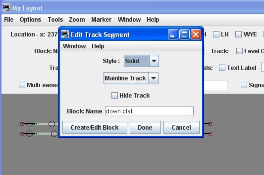
In the "Edit Track Segment" window, it is possible to change the track style to "Mainline", and give the track a Block Name. This name can be either a new one (and the Block will be created) or one produced earlier. Type in a new name, then use the "Create/Edit Block" button to bring up further editing options.
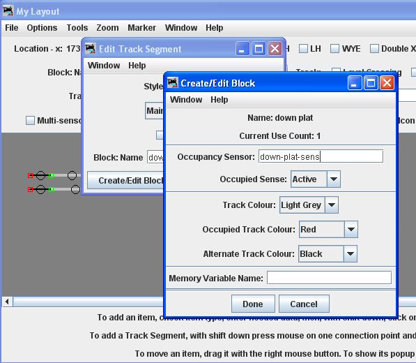
In the "Create/Edit Block" window, the sensor used for this block can be defined (from items in the Sensor Table), and also the colour of the track when occupied set. When this window, and its parent "Edit Track Segment" are closed with "Done" the results are saved.
Now, when a piece of stock triggers the occupancy sensor, the track segment should change colour to indicate that it is occupied.
If an adjacent track segment shares the same block sensor (a common occurance), then give it the same "Block: Name" value, and the "Create/Edit Block" window need not be opened.
The video below will show the Layout Editor, adding track segments and defining the block names and their associated sensors.
The download below contains the JMRI file for the work so far, it can be saved locally and opened with "Open Panels.." on the "Panels" menu of JMRI.