To get to our goal of full signal rules on our layout, we need to describe the signals to JMRI.
Signals exist as "Signal Masts". A Signal Mast follows the rules of the chosen prototype, thus for the UK it might be a four-aspect colour light, or a semaphore home signal. Each Signal Mast is made from one or more Signal Heads.
The simplest case has one Head on one Mast, for example a three-aspect Colour Light Mast consists of a three-aspect Head. Other cases may have several Heads on one Mast, for example, the three aspect Head and the call-on Head for the Mast controlling access to the bay platform. Or, a Mast with a Semaphore Home and a Semaphore Distant heads.
There is work on-going within JMRI to make it possible to directly define a signal Mast from the signal Mast table, without needing to define its underlying Heads. However, that is still in a very early stage, and we anticipate that most users will need to define the Heads for their signals.
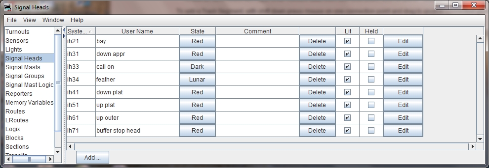
Signal Heads are created in the "Signal Head" table. In this table, a new Head can be added, and the decoder address(es) associated with the Head defined in the process. Each head has a System name which is prefixed "ih", though as with other elements, you should add a "User Name" to the definition for use later in JMRI. The decoder addresses created when adding a new Head will appear in the Turnout Table (where all accessory decoders appear). Once defined in the Signal Head table, the signal can have its aspects changed by clicking through the possible states. Some of the states may be illegal in UK signalling (eg. flashing red), but this is dealt with in the "Mast".
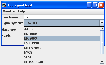
Once signal heads have been defined, they can be combined onto Signal Masts. With the "Add" command, the signalling system is selected, in our case BR (2003):
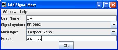
And then the Mast type is selected (3 Aspect), together with a User Name. The Heads used to make the Mast are entered in the lower field; if the Mast is made of multiple Heads then multiple Head fields will be presented:
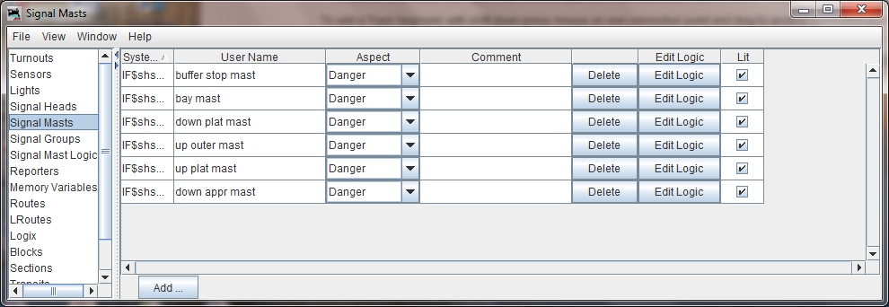
Once the Mast has been defined, it appears in the Signal Mast table, and the legal states can be changed from the table:
The creation of Signal Heads and Signal Masts is shown in the video below:
And the JMRI file with the Signal Heads and Masts created can be downloaded from the link below
With this little trick one can save considerably on the number of accessory decoders required to work UK style colour light signals. The simplest form works for two aspect (requires one decoder output) or three aspect (requires two decoder outputs). Similar tricks are possible for three aspect with flashing light, or four-aspect, but needs a few transistors or other components in the circuits.
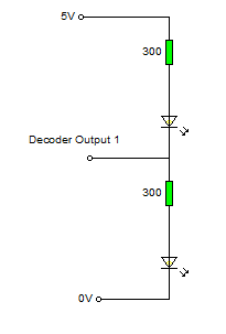
Two LED circuit. If the Decoder Output is "high" (5v) then the upper LED will be out, and the lower illuminate, and if the Decoder Output is "low" (0v) the upper LED will light and the lower will be dark. The voltage show (5v) depends on the type of accessory decoder, some may be 12v. The resistor values need to be adjusted to produce the required brightness from the LED.
A similar three LED circuit is shown below.
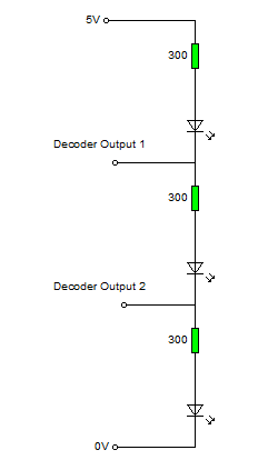
In JMRI, to make the three LED circuit work correctly, it may be necessary to select "invert" in the turnout table for one of the two decoder addresses.