The Manage VSD Locations window provides a consolidated location to manage and set the apparent physical location of sounds for trains using Virtual Sound Decoder
The Manage VSD Locations window has three tabs: Reporters, Operations Locations, and Listeners. Each tab shows a list of objects, each with a check-box to enable/disable use (for VSD purposes, not for other JMRI purposes), and entry cells for X, Y, and Z location coordinates.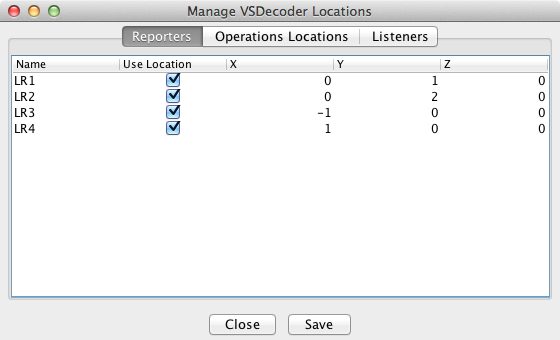
The Reporters tab shows a list of all currently defined Reporters. This is intended for use with Digitrax Transponding or other similar locomotive tracking hardware systems.
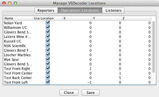
The Operations Locations tab shows a list of all Locations defined within the JMRI Operations system.
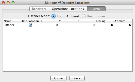
The Listeners tab shows the location of the Listener in the VSD sound system. The Listener position has two additional measurements: the Bearing (angle clockwise from the Y axis) and Azimuth (angle up or down from the X/Y plane) which together describe which way the Listener is facing.
With input from locomotive tracking hardware, Virtual Sound Decoder is able to move the apparent source of the locomotive sound to follow the locomotive's position on the layout.
Note: Reporters are not added to the Manage VSD Locations "live". If you add new Reporters, you must close and re-open the Manage VSD Locations window to make the new Reporters appear.
The VSD Locations system uses a standard "right handed" Cartesian coordinate system, where a location is defined by a combination of distances along an X, Y, and Z axis. The Origin, or center of the coordinates can be in any convenient location, such as the center of the room, a corner of the room, or a corner of the layout.
The X / Y / Z location values can be in any unit you choose, including an arbitrary relative scheme, as long as you are consistent. By default, positive X is to the space's right, positve Y is "forward", and positive Z is "up". Negative values are left, behind, and down, respectively. Alternately you may prefer to think of +X as "East", +Y as "North", and +Z as "up".
Note: The coordinate system can be rotated in any way that makes sense to the user. If it suits the railroad's arrangement better, +Y could be "East", +X "South", and +Z "Up". It is not recommended that the Z axis direction be changed however, unless your operators are accustomed to hanging from the ceiling.
A convenient system for a typical rectangular room-sized layout would be to place the origin at the near corner to the guest's left as the guest stands in the entry door, or the "bottom left" corner of the layout's track plan map, and with Z=0 at the layout's lowest nominal track elevation for the "live" part of the layout. This system ensures that all locations used will have positive X / Y / Z values.
If you do not specifically set the Listener location and orientation, the Listener by default will be at (0, 0, 0) and facing straight ahead along the +Y axis (bearing 0.0 degrees / azimuth 0.0 degrees). To set a different Listener location and/or orientation, go to the Listeners tab and set the X / Y / Z coordinates of the Listener's location. The coordinates and units must be the same as those used for the Reporters.
The Bearing and Azimuth values set the orientation of the Listener, or the direction the Listener is facing. Bearing is measured clockwise from the +Y axis. Azimuth is measured up (or down if negative) from the X/Y plane. Both measurements are in units of degrees of angle. For example, a Listener standing at the Origin (0, 0, 0) and facing "West" and halfway "up" would have a Bearing of 270 and an Azimuth of +45.
When you have followed the above setup steps, launch the VSDecoder Manager window, create a VSDecoder and run the locomotive. As your locomotive moves around the layout, the sound will follow the locomotive's reported position.
Note: The sound will appear to "jump" from location to location as the locomotive's reported location changes. This effect will be smaller with additional and more closely spaced reporters.
If you do not have a hardware tracking system, you can use the JMRI Operations feature to enable a rudimentary form of location following.
To set the Operations locations:
To use Operations for location following, assign the specific locomotive to the train, then select the train in the locomotive's VSDecoder Options pane. When you MOVE the train in Operations, the sound will move to the next location on the Route.
For more information on Operations, see the JMRI® Operations User's Guide
Note: Operations Locations following is temporarily disabled in JMRI 3.1.6 but will be re-enabled in 3.1.7.