To add a new Light:
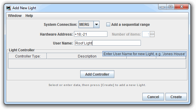
Click Lights in the Tables submenu of the Tools menu to bring up the Light Table, and click the Add... button at the bottom of the Light Table to bring up the Add Light window.
Select a System Connection if your layout is connected to more than
one system or to create an Internal Light.
Next enter the Hardware Address of your new Light (often entered as a
number, look at the Tooltip for accepted entry patterns per system).
This is the address JMRI will send to your system when switching the Light.
From this information, the program will make a System Name in the JMRI
convention, appropriate for a Light in the selected System using the entered address.
When you hover your mouse over the Hardware Address entry field, a tooltip will display
accepted entry example (depending on availability).
Some examples of valid System Names are: CL1004, and LL401 (entered as '401' here),
assuming you have the hardware for the addressed digital output bits.
CL1004
and LL401, assuming you have the hardware for the addressed digital output
bits.Enter a User Name. Any string of characters that is different from the User Name of other Lights will be accepted, but it's wise to use a string that describes the intended use of the Light. Entry of a User Name is optional.
If you wish to enter a Controller for your new Light, click the Add Controller button, and enter your choices into the Add Light Controller window which appears. You may enter as many Light Controllers as desired. More information on Light Controllers below.
Each Light Controller is displayed in the Light Controller table on the Add Light and Edit Light window. The Controller Type is shown on the left, followed by a Description of the Controller mechanism. These are followed by Edit and Delete buttons. Click Edit to bring up the Edit Light Control window allowing changes to the control specification as described above. Click a Delete button to remove a Light Controller.
Next is the notes area of the Add Light window. This is where instructions and error messages will appear as you create (or edit) a Light. Always check this area to see if things went as expected.
Click the Create button at the bottom of the window. If everything is
fine, a message stating "New Light added ... " will be displayed in the notes area. If
there is trouble with anything, an error or warning message will be displayed in the
notes area:
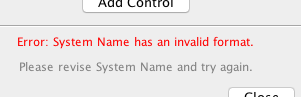
Correct the error and click Create again.
-OR-
Click the Close button to dismiss the window without creating any more Lights.
Adding several new Lights at once is optional.
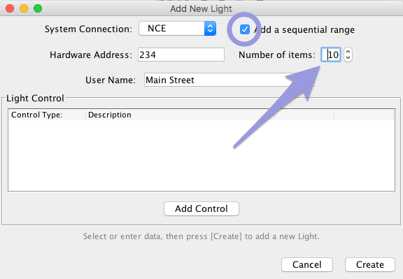
If you want to add several new Lights with sequential hardware addresses, check the
Add a sequential range check box.
When this box is checked, the Number of items: field is activated.
Set the number of Lights you want to add. Enter other properties for the first Light,
following the procedure above, and click the Create button.
Adding multiple Lights at once is intended to support stationary decoders which require several addresses in sequence. As a result, restrictions apply when creating several Lights at once. Note the following:
The addresses must be numerical -- only numbers are allowed in the hardware address.
The addresses of the created Lights must be consecutive.
If a User Name is entered, each of the created Lights after the first will have that User Name with ":1", ":2", etc. appended.
Entered Light Controller items and Variable Intensity items will be assigned to the first Light created, and not to subsequent Lights. These items may be added by manual Editing (see next paragraph).
Click on a Light's Edit button in the Light Table to bring up the Edit Light window:
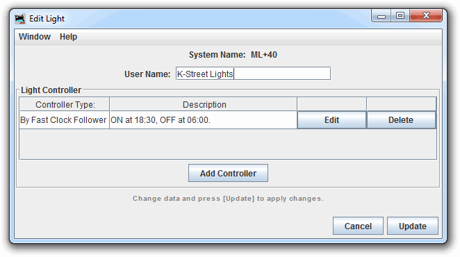
The System Name: of the Light is displayed at the top of the window
and cannot be changed once created.
The User Name may be changed either here or by double clicking on it in
the Light Table.
The Light Controller and notes areas are the same as above.
After making changes to the Light information, click Update to change the selected Light. If there is any trouble, an error or warning message will be displayed in the notes area, and the update is stopped for you to correct the error and click Update again. If all is fine, the Light is changed and the Add/Edit Light window is closed.
-OR-
Click Cancel to exit edit mode without changing the selected Light. If the Edit Light window is closed while in edit mode, Cancel is automatically selected, and no changes are made to the selected Light.
On startup, the status of Light Controller inputs will be checked, and the light will be
set to the appropriate state.
The Fast Clock Follower Light Controller uses the previous whole minute.
The Light Table contains an 'Enabled' column. For a Light Controller to be triggered it must be enabled, the default option on startup and Light creation.
You can uncheck this box to temporarily disable a Light from being triggered, i.e. prevent it switching when its control mechanism fires.
The Light Controller will not update status if the Light is disabled in the Light Table.
While adding or editing a Light, click on the Add Controller button.
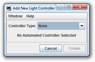
The Add/Edit Light Controller window is used to specify a Light controller. Automated operation of a Light can be controlled in one or more of the following ways:
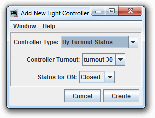
The Light will be turned ON when the Turnout changes to Closed or Thrown, depending upon the choice made in the Status for ON popup menu, and it will be turned OFF, when the Turnout reverses its status.
Select the Turnout in the Turnout Name dropdown.
This option may be used to set a fascia panel light to follow the status of a Turnout. That is useful, for example, for monitoring the status of hidden turnouts.
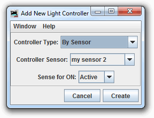
The Light will be turned ON when the Sensor changes to Active or Inactive, depending upon the choice made in the Sense for ON popup menu, and it will be turned OFF, when the Sensor reverses state.
Select the Sensor in the dropdown select.
This option has a number of uses, including setting a fascia panel light to follow block occupancy. That is useful, for example, for monitoring train position in a hidden staging area.
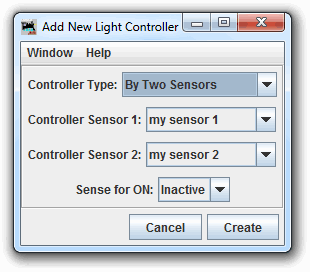
The Light will be turned ON when the either of the two Sensors changes to Active or Inactive, depending upon the choice made in the Sense for ON popup menu, and it will be turned OFF, when both of the two Sensors are in the reverse state.
Select each Sensor in the dropdown menu.
The order of entry does not matter.
This option has multiple uses, such as controlling crossing gates with point sensors that detect when a train passes. By placing two point sensors, one at each end of a bridge, a layout sound for a bridge rumble may be played while the train is traversing the bridge.
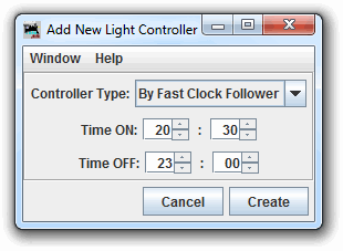
Each time the minute is updated, the Light Controller will check if the Light should be On or Off, and set the Light accordingly.
The Light will be turned ON when the Fast Clock reaches the time entered in Time On and will be turned OFF when the Fast Clock reaches the time entered in Time Off.
Hours are entered in "hh" format between 00 and 23.
Minutes are entered in "mm" format between 00 and 59.
One use of this option is to turn on and off scenery lighting, street lights, house lights, etc. to simulate night time on the layout.
If the light status is changed between minutes, it will be reset on the next minute update. eg.
This could be useful for the night-time random bathroom light scenarios, or even star shimmers. You'd only need 1 Sensor or Turnout Controller action to trigger the Light On, knowing that the FastClock Follower will reset it back to OFF pretty soon.
On startup, the Fast Clock will be checked, and the light will be set to correspond with the current time setting.
If no Fast Clock is present on your system, the current local time will be used.
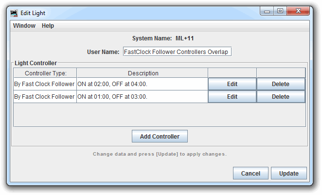
To stop one Light Controller turning the Light ON, and the other turning the Light OFF, only the most recent action time is used as the Light value, eg the following controls:
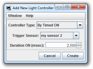
The Light will be turned ON when the trigger sensor changes to active, and it will be turned OFF, when the specified time has elapsed.
Specify the trigger Sensor by selecting its User Name (System Name if no User Name set) in the Trigger Sensor Name dropdown. Enter the time the Light is to remain on (in milliseconds) in the Duration ON field.
This option has a number of uses, it was originally designed to turn on an electromagnetic decoupler in response to a fascia pushbutton, but it can also be used for other types of layout animation, for example, to control the ringing of a crossing bell when a train enters a block.
Multiple Fast Clock Follower Controllers on a single Light will act as a group.
All other Light Controllers act independently, no matter what order they are placed in the list and may set the Light at any time, no matter the status of any other Light Controllers.
After setting a Sensor or a Turnout as part of a Light Controller, be very careful about changing the User Name of your Sensor or Turnout. A simple change of User Name could break your Light Control definitions.
If you enter multiple Light Controllers for the same Light, it is possible that the Light Controllers might conflict or overlap with each other, producing strange results. The user is responsible for ensuring that Light Controllers do not conflict.
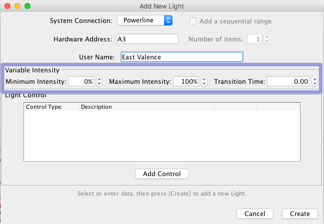
Systems like PowerLine, that support variable intensity lights also support lights with fixed intensity. If you are adding a Light with fixed intensity, i.e. an ON/OFF light, just leave the items in the Variable Intensity area as set. When editing a simple ON/OFF light on a system not supporting variable lights, the items in the Variable Intensity area are not displayed.
The intensity of a Light is represented internally by the range from 0.0 to 1.0, with 1.0 being brightest. Intensity limits are entered as percentages, from 0 through 100, in the Minimum Intensity and Maximum Intensity boxes. Because the actual light hardware has only finite resolution, the intensity value is mapped to the nearest supported setting.
Each Light has a Target Intensity property which can be set using a script or other code. Attempting to set the Target Intensity outside the Minimum Intensity to Maximum Intensity range will result in the Target Intensity being set to the relevant limit.
Light Control Tool (for manual Light operation)