The choice of hardware for a signalling project is very open, there are lots of makers of accessory decoders which can operate turnouts or signals. The choices used in this tutorial are NOT the only ones which could work, just those the authors happened to have available at the time.
To allow our signals to operate automatically, we require a means of controlling them from JMRI. Therefore, our signals are controlled by an accessory decoder which is addressed by commands from JMRI.
The Signal Mast Logic must know the state of the turnouts, otherwise it cannot set a signal correctly, so our turnouts are also controlled by accessory decoders.. Additionally it is desirable to know whether the track ahead of a signal is occupied. so we require a means of detecting block occupancy.
For the tutorial, we constructed a system based around LocoNet. LocoNet includes the ability to send information back to the command station and computer running JMRI. In our case, we used this to send back occupancy information.
Our Command Station is a Digitrax Zephyr. This is linked to the computer running JMRI using a Digitrax PR3 computer interface. The turnouts are controlled using a CML Electronics DAC20 accessory decoder. In addition, that decoder can accept input from occupancy detectors, so we used a Digitrax BD4 occupancy detector to monitor four track sections. Our colour light signals are controlled using a LocoIO board (from Hans De Loof), and the Semaphore Signals are controlled by a LocoServo board (also HDL). The LocoServo has a few spare inputs on our demonstration, so we used those for push-buttons to set routes - thus there is a push button interface to set the track.

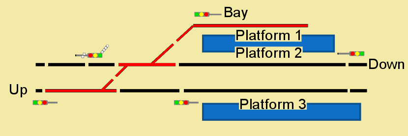
The arrangement of blocks is shown below, with the three track segments coloured red linked to individual inputs on the BD4 detector (the fourth input was not used). The blocks which are coloured black were used in software but not attached to hardware detectors. With the hardware detectors, the system can tell that a train is in the bay, crossing the junction, or on the Up line before the west-most signal.
It is quite possible to operate without any hardware detectors, and instead use the user interface onto a Panel in JMRI to operate "internal" sensors which are attached to blocks. Thus a human operator tells the system that a block is occupied or clear, and the system will then calculate the correct signal settings.
The video (hosted on YouTube) gives an overview of the layout and its hardware.