The Signal Mast Repeater tool allows you to configure one Signal Mast to follow the state of another, or for a change on either Signal Mast to force the other to the same state.
Signal Mast Repeaters require that both Signal Masts must be of the same Signal System and the same Mast Type. Signal Mast Repeaters cannot be configured between masts of differing types or between signaling differing signaling systems.
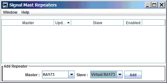
The Signal Mast Repeater table is accessed via the "Tools" pull-down menu at the top of the Signal Masts Table window.
When creating a new Repeater, and a Master mast is selected from the pull-down list at the bottom of the window, the Slave pull-down list will be populated with Signal Masts of the corresponding signaling system and mast type. If there are no valid masts then the option to select the Slave will remain disabled, with an empty list.
Once both a Master mast and a Slave mast have been selected, the "Add" button may be activated to add the Repeater to the list at the top of the window.
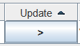
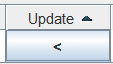
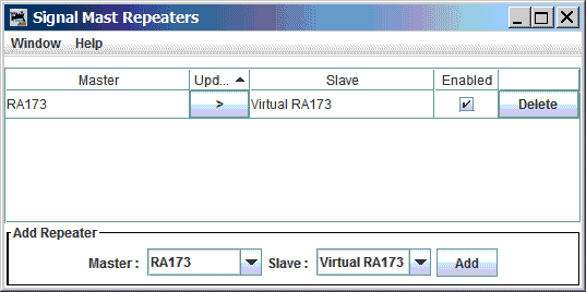
The "Repeat" function may operate in any of three modes which define the direction(s) in which the "repeat function" occurs. The direction of repeat for a given Repeater is configured in the upper part of the Signal Mast Repeater tool window using a button in the column named "Update" This column is typically found between the master and slave name columns. Activating the button sequences through the three available modes. Each mode is shown on the button by one or two arrow-like representations of the direction in which repeats are made:
|
indicates that Master mast aspect changes are repeated to the Slave mast. |
|
indicates that Slave mast aspect changes are repeated to the Master mast. |

|
indicates that any Master mast aspect change is repeated to the Slave mast, and any Slave mast aspect change is repeated to the Master mast. |
By default, a Repeater is enabled when it is created. It is possible to disable an individual Repeater by un-checking the box in the "Enable" column for the particular row containing the Repeater. This can be useful for debugging your Repeater's effect on the layout.
In those cases where there are multiple routes between a "source" signal mast and a "destination" signal mast, with no intervening signal masts, the regular JMRI Signal Mast Logic "discovery" project will only identify one of the valid routes. JMRI's Signal Mast Logic ignores any other existing routes and does not generate any logic in the Source mast's logic for those un-discovered routes.
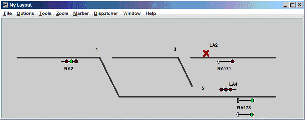
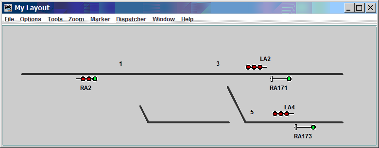
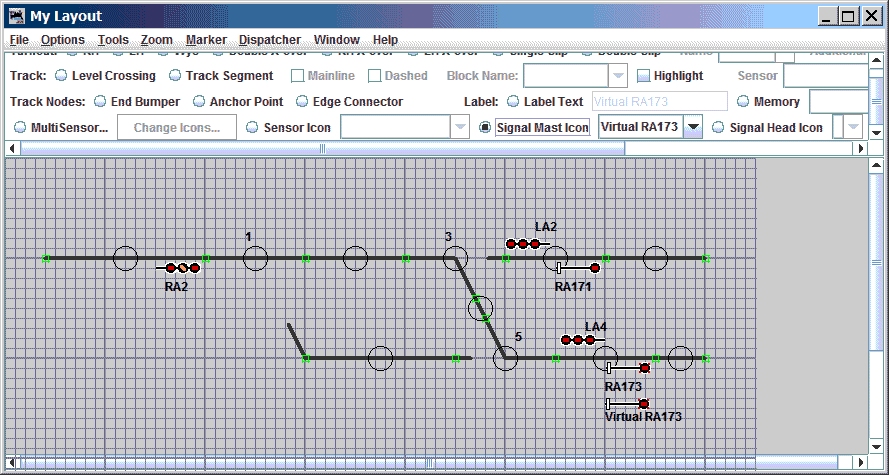
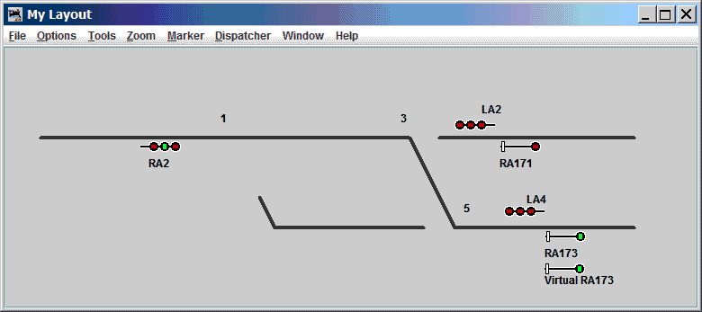
The Layout Editor panel below shows a track arrangement where this Signal Mast Logic discovery shortcoming can be seen. For this panel, there are three different routes from signal RA2.
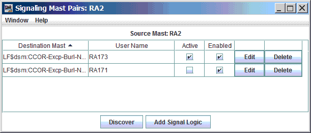
JMRI's Signal Mast Logic "discovery" finds only two of the three routes:
JMRI Signal Mast Logic Discovery for RA2 fails to automatically discover the last route:
Each of the three routes is separately discussed below.
This route is from signal RA2, via switch 1 "reversed" (thrown), and switch 5 "normal" (closed), to signal RA173, and is shown below.
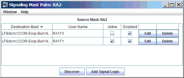
Route 1 was properly discovered by the Signal Mast Logic and is shown in the top row of the Signal Mast Logic window image, below. the Route 1 logic is enabled (checked). Under the conditions shown in the image above, Route 1 is currently an active route, as indicated by the associated check marks. Examination of the conditions shown above shows that RA2 is presenting a "Diverging Clear" aspect (Red over Green over Red).
This route is from signal RA2, via switch 1 "normal" (closed), and switch 3 "normal" (closed), to signal RA171, and is shown below.
Route 2 was properly discovered by the Signal Mast Logic and is shown in the second row of the Signal Mast Logic window image, below. The Route 2 logic is enabled (checked). Under the conditions shown in the image above, Route 2 is currently an active route, as indicated by the associated check marks. Examination of the conditions shown above shows that RA2 is presenting a "Clear" aspect (Green over Red over Red).
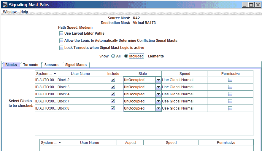
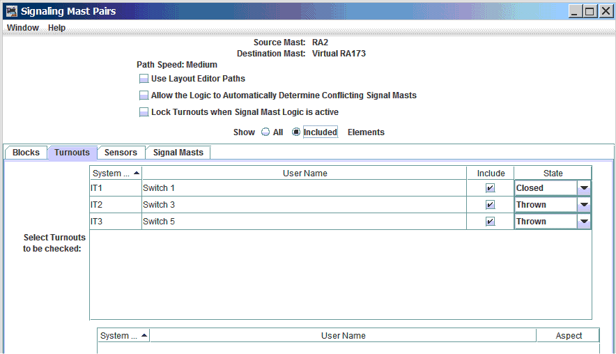
Route 3 is not discovered by the Signal Mast Logic. This route is from signal RA2, via switch 1 "normal" (closed), switch 3 "reversed" (thrown) and switch 5 "reversed" (thrown) to signal RA173, and is shown below.
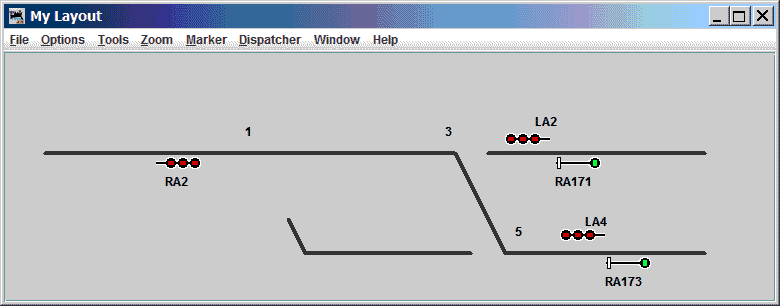
Note that signal RA2 does not give an indication better than "Stop" under these conditions, because there is no Signal Logic entry which discovered the path from RA2 to RA173 via this route.
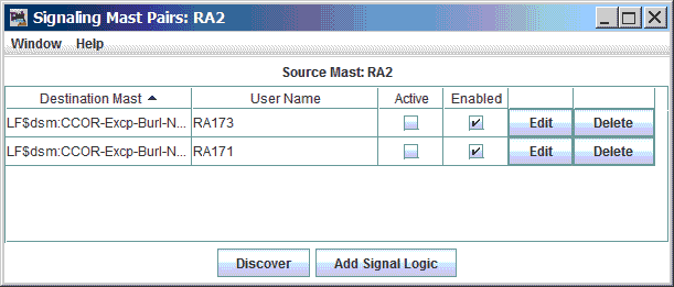
Note that neither of the two rows of the Signal Mast Logic table shown above are marked as "Active", because the route requirements of these two Signal Mast Logic entries are not met.
When discovering signal mast pairs between which to create Signal Mast Logic, JMRI finds only one path between a given signal mast pair. JMRI's discovery process then stops looking for other paths between those two signal masts, and moves on to discovery for another signal mast pair.
There are a variety of technical reasons for this behavior, and, at least for the near future, there is no expectation that this behavior will change. A workaround is needed.
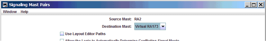
That explanation of the problem contains a hint on how to resolve the problem - JMRI's Signal Mast Logic works with unique pairs of signals. This implies that a signal mast which duplicates the behavior of RA173 might allow Signal Mast Logic to be created for the undiscovered route from RA2 to RA173.
The duplicate of signal mast RA173 turns out to be a great idea! And it is the beginning of the solution!
But a given point on a Layout Editor panel can only have one signal mast governing movement in a given direction. That means that the duplicate signal mast cannot be tied to the same spot on the panel. And, in a roundabout way, it also means that Signal Mast Logic discovery is unable to automatically identify the alternate path to the the duplicate of RA173.
Proceeding from this point requires manual work - it is necessary to manually create the Signal Mast Logic entry which we would have preferred that Signal Mast Logic discovery would create. That's where the "Add Signal Logic" button on the signal's "Signal Mast Logic" window comes into play.
The steps to work around the Signal Mast Discovery shortcoming described above are:
The steps are detailed here:
Click on that button to cycle the arrowheads so that there is only one arrowhead, and it should point towards "Virtual RA173". This means that changes to RA173's indication will be reflected upon Virtual RA173, but that changes on Virtual RA173 will not be reflected upon RA173. This is shown below.
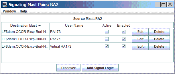
The resulting Signal Mast Logic list for RA2 appears similar to the image below, although the "Active" logic item may be selected differently, or no "Active" item may be shown, depending on layout conditions.
The speed settings for the turnouts and blocks in a given path all can influence the aspect shown on the signal. The slowest speed on any part of the route will limit the signal indication to one which allows that speed (or some lower speed, if that specific speed is not available by signal indication).
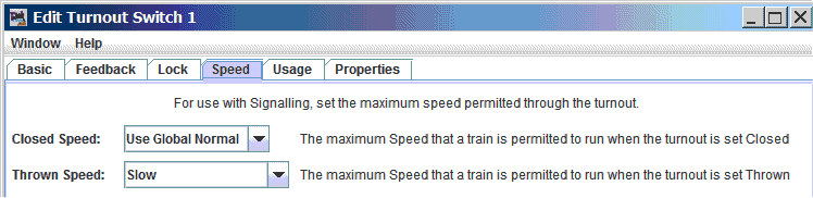
Note:If the individual turnouts are left at JMRI's "default" values, then any route with a diverging turnout will automatically force the signal to a maximum speed of "restricting" for the route. To achieve the images shown above, it was necessary to change the turnout "diverging" speeds (in the Turnouts table) to be at least "Slow", as shown below. For the selected signaling system, that was sufficient to allow the signal mast logic to choose "Diverging Clear" (Red-Green-Red) for those routes where a switch required a diverging route.
This concept can be extended to situations where "n" routes are available from one signal mast to another signal mast. With "n" routes, discovery will only find one of those "n" routes. Using the workaround described above, it is necessary to create "n-1" signal mast repeaters for the destination mast. And it is necessary to manually create "n-1" Signal Mast Logic entries from the source signal mast to each of the virtual copies of the destination mast. (The example given above is described the case where the value of "n" was 2.)