Circuit Builder
Since 2.12
The Circuit Builder is a view of a Control Panel Editor panel (CPE in short). CB is an
alternative to using the Occupancy Block Tables to
create OBlocks, Portals and OPaths. Circuit Builder is a graphical tool to
create and configure these objects by "point and click" mouse operations on your CPE panel.
Here "track circuit" is just another name for "OBlock". The prototype name for track having a
device that can detect occupancy is Track Circuit. In JMRI we have used the
term "Block" and "OBlock" to refer to what in the prototype world is a
track circuit. The term Block in the prototype world is a length of
track defined by limits, whose use is governed by block signals, cab signals or block limit
markers and train orders. That is, a prototype block incorporates a signaling system
providing a way to manage safe usage of its trackage. So to model a prototype block, several
track circuits may be needed. The term track circuit here in JMRI is just an
attempt to get a little closer to prototype usage, but it is just another name for
OBlock and the stuff (Portals and OPaths)
that gets it to act a little more like a prototype "Block". Creating track circuits, that is,
making and configuring OBlocks, Portals and OPaths enables the creation and running of
Warrants.
Since 4.17.3
Circuit Builder can also be used to place Signal Masts or Signal Heads at Portals to display
aspects and appearances that indicate track conditions on your layout. These signals then can
modify Warrants during their runtime to respond to track conditions. More on this below.
Getting Started
The Circuit Builder tool can be opened from either the
Circuit Builder menu
item under the
Add Items menu or by the
Open Circuit
Builder menu item under the
Warrant menu. These menus only show
when a Control Panel Editor panel is displayed.
In CPE make a track diagram of your layout using track icons - of any kind, but eventually
they will need to be some kind of Indicator Track. If you already have made a Panel Editor
panel, refer to CPE Help how to open it in CPE
view.
The Item Palette menu item under the Add Items menu can
help you select the kind you want. Then open CircuitBuilder as suggested above. The
CircuitBuilder menu will appear. Now use either the Circuit Builder window or the Circuit
Builder menu to make two track circuits (OBlocks). At least two OBlocks are needed before any
Portals or Paths can be made, so until then the menu is restricted to menu items
- Add New Detector Circuit
-
Add/Edit OBlocks
- CircuitBuilder Help, which will open this help page
As soon as two or more items have been created in the OBlock table extra items are
visible
Basic Operational Model of Circuit Builder
Circuit Builder works by using icons on a block by block basis. OBlocks, Portals and OPaths
are created and linked by "point and click" on the icons of your layout diagram. The element
types (OBlock, Portal, OPath, Signal) are created and edited using various editing modes of
the tool. In short, it works as follows:
First create an OBlock by selecting track icons. Then create Portals by dragging an icon
that overlaps two OBlocks. Then create OPaths by selecting the portal icons and track icons
that indicate the path. Finally perhaps add a signal to protect an OBlock by selecting the
portal of the approach. The result of this editing transforms the track in your layout panels
to indicator trackage displaying the states of the blocks and their paths by color without
altering the original look of the panel. These operations are done from the CircuitBuilder
menu items and are detailed below.
Panel files previously made with Panel Editor can be used with Circuit Builder as long as
they can be loaded into this version of JMRI. Circuit Builder will guide you to upgrade plain
track icons to Indicator Track icons. See the Item Palette
help for more information about Indicator track icons.
CircuitBuilder is aware of all the objects defined in the Occupancy Block tables. When
your layout track diagram is split up among several panels, each panel has a its own
CircuitBuilder to edit its icons. It may post messages about missing icons but if the objects
are not meant to be represented on that panel, ignore them. This "discrepancy" is due to the
fact that OBlocks, Portals and Paths are global for all panels of your JMRI session, but each
Circuit Builder is concerned only by the icons on its panel.
Mouse Operations When Using CircuitBuilder
When you are in Circuit Builder editing mode, the mouse click conventions differ somewhat
from those of the panel editors. When a Circuit Builder menu item is selected an editing
window is opened and the panel is in a Circuit Builder editing mode. Note the following when
in a Circuit Builder editing mode:
- Dragging is not supported except for portal icons when creating or editing Portals or
configuring a Signal Mast.
- Most Control Panel Menus are disabled.
- Only track or portal or signal icons can be selected.
Portal Icons
When not in one of the CircuitBuilder editing modes, portal icons are usually invisible. The
only situation in normal panel operation where they may be visible is when a warrant is
allocated. In this case direction arrows can be shown indicating the direction of travel of
the warranted train. Portal icons are necessary for CircuitBuilder to be able to define
Portals and OPaths. In such editing modes the icon is usually a red circle that may be
dragged or selected.
Note: It is important for defining paths that every
track circuit depicted on the panel have each of its portals represented by
a portal icon.
The Circuit Builder Menu
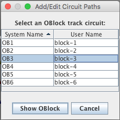
After two track circuits (OBlocks) have been created the full Circuit Builder menu appears.
Selecting a menu item will first ask you to select an OBlock from a pick list.
Click [Show OBlock] to continue.
- Add New Detector Circuit - Create an OBlock track circuit and assign
the icons that display it, then continue with the editing of the Circuit OBlock data.
- Edit Circuit OBlock - Edit an existing track circuit. In this window
you select or deselect the track icons that represent the OBlock graphically. Names of the
sensors that detect occupancy or errors should be entered as well as a length for the
block. (Warrants need a length for the paths to calculate speed changes.)
- Add/Edit Circuit Portals - Create or edit Portals connecting two track
circuits. After choosing an OBlock, you will be in portal editing mode. In
this window you define Portals by positioning them over track icons to connect
OBlocks.
- Add/Edit Circuit Paths - Create or edit the paths (OPath) through a
track circuit. After choosing an OBlock you will be in path editing mode.
In this window you define OPaths by selecting track and portal icons.
- Edit Portal Direction Icons -
(since 3.8) Choose arrows to indicate the direction of a Warrant
route through a block. After choosing an OBlock you will be in portal icon
editing mode. In this window you configure portal icons so they show the direction
of travel when a warrant is allocated.
- Add/Edit Signal Icons - (since 4.17.3) Attach a Signal Mast to a Portal whose OBlocks are the
approach block and block protected by the the signal. After choosing an OBlock you will be
in signal icon editing mode.
-
Error Checks - Provides information about objects
that may require editing. These menu sub-items either highlight the icons representing
the object or display a list of track circuits or Portals that may require editing.
Selecting an item from such a list will open a window for the appropriate editing mode.
- Circuits without icons in this panel - Has a submenu for each
track circuit OBlock that does not have an icon. A track circuit needs at least one
Indicator Track icon to display its state.
- Circuits whose icons need conversion - Has a submenu for each
track circuit OBlock whose track icons are not Indicator Track icons.
Note: Only Indicator Track icons can display circuit state
information.
- Highlight track icons needing conversion - Highlights all track
icons that are not Indicator Track icons. If all track icons are Indicator Track icons,
this menu item it labeled All track icons are Indicator icons
- Highlight Indicator Track icons without circuits - Highlights all
track icons that are not associated with a track circuit. If every track icon is
associated with a circuit this menu item is labeled All track icons belong to
Circuits
- Circuits without a Portal or Path - (since
4.17.3) Has a submenu for each track circuit OBlock that does not have a Portal
or Path. Select an item to add the required portal or Path.
- Circuits with misplaced Portal Icons - (since
4.16) Has a submenu for each track circuit OBlock that has a Portal icon
positioned incorrectly.
- Highlight misplaced Portal Icons - Highlights all portal icons
that are not positioned correctly. If every portal icon is positioned correctly this
menu item is labeled All Portal icons positioned OK
- Portals without icons in this panel - (since
4.16) Has a submenu for each Portal lacking an icon. Selecting an item opens a
Portal Editing window and an icon can be dragged onto the panel.
- Highlight Signals not configured to protect an OBlock -
(since 4.17.3) Highlights all signal icons not protecting an
OBlock at a Portal. If every signal icon provides protection correctly this menu item
is labeled All Signal icons positioned OK
- Check Portal and Path errors - Examines the Portal and OPath
definitions looking for errors or incomplete information. A dialog box is displayed
listing any errors found.
- Change Portal Icon Set - (since 4.21.1) The
icons used for Portals may be changed or alternative icon sets created. If there are
additional sets of portal icons the set to use can be chosen here.
- CircuitBuilder Help - Opens this help file.
Notice that except for the first and last three menu items, first you choose the OBlock, and
then edit the chosen element (OBlcock, Portal, Path, Arrow, Signals). For editing these items
a picklist is opened for you to select a circuit OBlock to edit. Selecting a row and pressing
the
Show OBlock button then opens the window for the desired editing of that
block.
Rather than having to do that for each editing operation, for convenience, the
Warrants menu item Open CircuitBuilder keeps a widow open
with the block pick table and the various editing modes available from radio buttons.
How to Make OBlocks, Portals and OPaths
Creation and editing of these objects is done is with the editing modes of Circuit Builder.
The editing windows contain some text to assist you when using them.
Creating OBlocks
From the Circuit Builder menu select the Add New Detector
Circuit menu item. This opens a dialog for you to create a circuit OBlock by
supplying its system and user name. The window has fields to enter the system and user names
for a new OBlock. After pressing the Create OBlock button, the System Name
field will disappear and the button will be replaced with buttons that will allow you to
change the user name or delete the block. The window is now appears as Edit Circuit
OBlock menu item.
Editing OBlocks
The Edit Circuit window used is to identify the track icons will display the track circuit
and to enter the data needed for it to function.
In this mode, mouse clicks on a track icon in the basic window frame toggles selection of
the track. Select the icons you want to use to display the track circuit. The icons for a
track circuit typically are, but need not be, contiguous. The icons that display the circuit
are highlighted in blue. Icon types other than track icons cannot be selected. No icons can
be dragged.
- At the top of the window is a non-editable field to show the current state of the
circuit.
- The window has a text field showing the OBlock User Name. The field can be edited to
change the user name of the OBlock circuit. Below it is a Change Name
button to accomplish the name change.
- Alongside is a Delete Circuit button to delete all components of the
track circuit. Note this means, the OBlock, all the
OPaths in it and all portals into and out of the block.
- The window also has convenience fields that count the track icons that are selected for
the circuit.
- When adding or editing a circuit, the window has text fields to name the sensor that
will detect occupancy and a sensor that can indicate errors. Each of these sensors are
optional and can be entered later. There is an Open Picklist button to
display sensor names that can be dragged and dropped onto the sensor name text fields. If
no occupancy detection sensor is named, the circuit will be a Dark Block.
Warrants are able to start, end or pass through dark blocks.
- The window has a text field to enter the length of the OBlock and button for either
inches or centimeter units.
Note: In order to create and run NXWarrants over a block, the block
must have a length. Running recorded warrants also needs block lengths to compute ramp
parameters when responding to signals and other track conditions
- The Convert Icons button will convert the icons in the circuit to
Track Indicator icons if they are not already icons of this type. This can be done later.
Converted icons may need to be rotated and repositioned.
- The Done button completes the creation and editing of the track
circuit.
When exiting the Edit Circuit window the OBlock is checked for any possible deficiencies.
If any are detected you will be prompted and given the option to return to the window or
continue to close it. Note: Each OBlock must have at least one Indicator
Track icon to represent it. Otherwise CircuitBuilder cannot define Portals and
Paths.
Portals - Add/Edit Circuit Portals
Use this window create and edit portals. A portal is represented by a red circle icon. The
track circuit icons are highlighted in blue. if any Portals have been defined, they will be
shown as a red circle and also highlighted in blue. The blocks a portal connects are
determined by positioning the icon so it spans the two blocks it connects. That is, the icon
should overlap a track icon representing each of the two blocks. In this mode, only portal
icons can be repositioned. No other panel items can be moved or selected.
To create a new portal type in a name for it in the Portal Name text
field. Then drag the red circle portal icon to the panel. Place it so that it intersects with
a track icon representing the OBlock you selected to open the window. The OBlock circuit you
selected is the "home" block. Position the portal icon so it also intersects with a track
icon representing an adjacent block. Overlapping both blocks defines the portal.
To create an icon for a portal previously defined, perhaps from the Occupancy Block
tables, select the portal from the "Portals into and out of circuit ..." list. Then, as above
drag and position the red circle icon.
Notice that when you select a portal from the portal list, its icon highlight changes from
blue to pink. Conversely, selecting an portal icon on the panel with a mouse click will
select the portal it represents in the portal list. When repositioning a portal icon it may
be necessary to "unlock" its position.
There may be diagrams where a portal icon cannot span icons from each block that the
portal connects. An example of this might be when the panel diagram depicts a loop as a line
of blocks across the panel from left to right. Here a leftmost block icon cannot be spanned
by one from the rightmost block. This can be handled in one of two ways. A non-contiguous
track icon could be placed from one edge onto the opposite edge of the diagram and a have the
portal icon overlap both blocks there.
(since 4.17.3) Or two portal icons can be used
for the same portal. Each icon placed on the respective blocks at the opposite sides of the
diagram.
- The Edit Portal window has a list of the portals already defined for the track circuit
(OBlock) and a text field to name new portals to be created. The window also has a icon to
represent portals as a red circle in the main window.
- The text field can be used to change the name of a portal with the Change
Name button to accomplish the name change.
- Portals are created by naming them in the text field and dragging the red circle icon
to its position between the two track circuits it connects. After dragging the icon into
position the portal is listed in the Portal List.
- Portals that were created in the Occupancy Tables do not have red
circle icons. For any portal in the Portal List that does not have an icon, select it from
the list and drag a red circle icon to its position between the blocks it connects. Portal
icons are needed to create and display paths.
Note Please be sure all of the OBlock's portals are
represented by icons before making paths.
- To change the name of a portal, first select it from the list, then change the name in
the Portal Name text field and lastly, press the Change
Name button.
- To delete a portal, select it from the list and press the Delete
Portal button.
- The Done button completes the creation and/or editing of Portals.
When exiting the Add/Edit Portal window the Portal is checked for any possible
deficiencies. If any are detected you will be prompted and given the option to return to the
window or continue to close it.
Paths - Add/Edit Circuit Paths
Use this window is to create and edit the paths in the track circuit. In this mode, no panel
items can be moved. The track circuit icons are highlighted in blue and the portal icons are
shown with a red circle highlighted in blue.
To create a new OPath, first press the Clear Selection button. Then type
a name for the path into the Path Name text field. Now select all the track
icons that mark the route. Selected route icons change their color to green. When selecting a
turnout track icon, the position of the points may not be correct. To change the
position of the points, hold the Shift key down while clicking
on the turnout icon. At least one portal must be selected to complete the definition of an
OPath. A selected a portal icon changes from a red circle to a green square.
Be sure you select all the turnout icons for turnouts that need to be set to define the
path. Also, if the path traverses the block, be sure that portal icons are selected for both
entrance and exit. A path must have at least one portal and at most two.
If the value of the Length text field is "0.0" the length of the path
will be inherited from the value of what was entered for the length of the OBlock circuit. If
the length of the path is significantly different from the OBlock length (i.e. by more than
10%), enter a length for the path. Note: Path lengths are needed for a
warrant to calculate where to begin a speed change required by a signal aspect or block
occupation ahead of the train.
- The Edit Paths window has a list of the paths already defined for the track circuit and
a text field to name paths to be created.
- The text field can be used to change the name of a path with the Change
Name button to accomplish the name change.
- Paths are created by selecting the icons that display the path. The selected icons are
displayed green. A second mouse click deselects the icon.
- When selecting a turnout icon for the path, it needs to have its points set correctly.
To keep the icon selected green when you throw the switch, hold the Shift Key down when
clicking with the mouse. This keeps the selection green while throwing the switch.
- It is important that portals for the entrance and/or exit of the path be selected also.
When a portal icon (red circle) is selected it turns into a green square. A path may have
one portal selected, if it is a stub siding but must have two portals selected (entrance to
and exit from the block) if it is a through path.
- To change the name of a path, first select it from the list, then change the name in
the Path Name text field and lastly, press the Change
Name button.
- The window has a text field to enter the length of the OPath and button for either
inches or centimeter units.
- To delete a path, select it from the list and press the Delete Path
button.
When exiting the Add/Edit Path window the Path is checked for any possible deficiencies.
If any are detected you will be prompted and given the option to return to the window or
continue to close it.
Portals - Edit Portal Direction Icons
Since 3.8
Use this window to modify the portal icon to show the direction of travel for a warrant.
Portal icons must exist in order to have direction arrows when a warrant is allocated. The
track circuit icons are highlighted in blue and the portal icons are shown with a red circle
highlighted in blue.
To set the direction, either select a portal icon or select a portal from the "Portals
into and out of circuit ..." list. A green arrow will replace the red circle on the
highlighted portal icon. To have the arrow display the correct direction the arrow must point
into the OBlock circuit. If it does not, select one or the other of the
green arrows on the Entry Icon box. The arrows can be moved and rotated to
display a more desirable direction. If an icon is moved, be sure it retains its position
overlapping the blocks it joins.
If you do not want an arrow to display at the portal when a warrant is allocated, select
the "No Icon" icon.
After all the portal icon arrows are pointing into the block, verify that each adjacent
OBock also has its portal direction arrow set into that block.
Signals - Edit Signal Masts
Since 4.17.3

Use this window to configure a Signal Head or Signal Mast to protect the
OBlock. The track circuit icons are highlighted in blue and the portal icons are shown with a
red circle highlighted in blue.
To set a signal to protect the OBlock, choose the portal where the signal will guard
entrance into the block. The opposing block of the portal will be the approach OBlock.
Choosing the portal can be done by either selecting a highlighted portal icon or selecting a
portal from the "Portals into and out of circuit ..." list.
Enter the name of the signal into the Signal Name text field.
Alternatively there are Open Picklist buttons to display signal names. Drag
a name into the Signal Name text field. Pressing the Configure Signal button
will attach the signal at the portal.
Important Note:
It is recommended to use Signal Masts rather than Signal Heads. If you do use a Signal Head
be sure it is not part of the definition of a Signal Mast. Signal Head
appearances are translated to speed names according to to a table in Warrant Preferences.
Then, as above, the speed name is used to regulate train speed.
The signal add/edit window has the following items.
- A list of the portals into the OBlock. Select a portal to add or remove the block
protection by a signal. If a signal already protects at the selected portal, its name is
displayed in the Signal Name text field.
- A Signal Name text field for the name of a protecting signal.
- Buttons to set block protection or remove it.
- Buttons to display pick lists for dragging signal names into the Signal Name text
field
- A text field to adjust the target point a warrant calculates for the place where a
speed change should start, if a signal aspect requires it. (Speed changes required in a
protected block must be completed before entering the block.) The number is an offset from
the portal entrance point to the block. It may be positive or negative.
Selecting a signal icon will select the portal if it protects the block there. Otherwise a
dialog windows opens to configure or replace protection.
Further Reference