JMRI software, including DecoderPro and PanelPro, works with your Digitrax command station to program decoders. To do this, it communicates with the command station over the LocoNet® using one of several types of adapter.
JMRI software supports the following LocoNet-based command stations:
For systems which do not provide a real LocoNet Command Station, two additional options
are supported. When a layout uses LocoNet peripheral devices but not a LocoNet-based command
station, a "Standalone LocoNet" is used.
In addition, JMRI software may be configured to use a simulated LocoNet connection instead of
a real LocoNet connection. This is the "LocoNet®
Simulator".
To connect your computer to the LocoNet, and hence to the command station, you need one of the following adapters:
(Note: The Digitrax DSC240 has a built-in adapter that's similar to the Digitrax PR3; if you have a DCS240 and connect the computer via the DCS240's integrated USB interface, see this DCS240 page. Similarly, the Digitrax DSC52 has a built-in adapter that's similar to the Digitrax PR3; if you have a DCS52 and connect the computer via the DCS52's integrated USB interface, see this DCS52 page.
Generally, any of these can be used with any type of computer to communicate with any type of command station. Currently, the LocoBuffer-NG , PR3, and PR4 are the recommended computer interface solutions. The LocoBuffer II and original LocoBuffer are no longer commercially available; their primary advantage now is that they use a traditional serial port, which may be the only suitable connection type available on some older computers.
The MS100 is not recommended; it sometimes fails to provide reliable communications, and it cannot be used with JMRI if you are using Mac OS X or on most Windows Vista machines. If you have problems with the MS100, you might not be able to fix them, and nobody may be able to help you.
The Uhlenbrock Intellibox command stations can also be controlled directly through it's serial port or USB connection; there's a separate page on how to do this.
Uhlenbrock Intellibox - The Intellibox has two LocoNet connections, called LocoNet-T and LocoNet-B. The LocoNet-T connection can drive more devices, but does not provide the Rail-Synch signals that some LocoNet devices (particularly boosters and the BDL16, BDL162 and BDL168) require. A LocoBuffer should be connected to the LocoNet-T connection.
Uhlenbrock Intellibox II and IB-Com - The Intellibox II and IB-Com have two LocoNet connections, called LocoNet-T and LocoNet-B. The LocoNet-T connection can drive more devices, but does not provide the Rail-Synch signals that some LocoNet devices (particularly boosters and the BDL16, BDL162 and BDL168) require. A LocoBuffer should be connected to the LocoNet-T connection.
PR-1 not supported - Note that DecoderPro cannot directly program decoders via a PR1 programmer. JMRI supports decoder programming either via the PR3 as a stand-alone programmer or via a command station.
Mac OS X and the MS100 - Because Mac OS X can't communicate at the special baud rate used by the MS100, the MS100 won't work with Mac OS X. You should get a LocoBuffer-NG or LocoBuffer-USB instead.
Microsoft Vista and the MS100 - It has been reported that Vista does not support the special baud rate used by the MS100. If you find that your MS100 does not work on your Vista machine you should get a LocoBuffer-NG, LocoBuffer-USB, PR3, or PR4 instead.
To connect your computer to a Digitrax DCC system, you need either a USB-equipped Command station (DCS240 or DCS52), or a computer-to-LocoNet adapter device such as a LocoBuffer-NG, PR3, PR4, LocoBuffer-II, LocoBuffer or MS100. The LocoBuffer-NG is a highly recommended computer-to-LocoNet adapter. See below for more on adapters.
Note that except for the PR3 and PR4, these are only LocoNet interfaces, not stand alone programmers like the Digitrax PR2. The Digitrax PR3 and PR4 devices may act either as a standalone programmer or as a LocoNet interface. Readback of decoder CVs is possible when using a programming track controlled by a PR3 or PR4 (in stand-alone programming mode) or when using a programming track controlled by a Chief, Zephyr, Advanced (DCS210) or Evolution (DCS240) command station. The Empire Builder (DB150) command station does not allow Readback of decoder CVs; users of the Empire Builder can add CV Readback capability by using a programming track connected to a PR3 or PR4 when operating in stand-alone programming mode.
If connecting to a DCS240 command station via its integrated USB port, see these instructions for configuring JMRI for the DCS240.
If connecting to a DCS52 command station via its integrated USB port, see these instructions for configuring JMRI for the DCS52.
The steps below show how to add a connection to JMRI (DecoderPro, PanelPro, etc.) for a LocoNet-based system.
When the "Connection Type" is set for the PR3 or PR4, the "Command Station Type" can be set to "PRx in stand-alone programming mode" or set to one of the command station types. When set for stand-alone programming, the PR3/PR4 will not communicate with LocoNet. When set for a specific command station type, the PR3/PR4 programming track is not used; instead, decoder programming is done through the mechanisms provided by the selected command station, and its programming track connections.
When "DB150 (Empire Builder)" is selected, JMRI decoder programming is done via the DB150 programming mechanisms. The DB150 is not capable of reading decoder CV values, so JMRI will not be able to read decoder CV values via the DB150 programming mechanisms. Empire Builder users can use a PR3/PR4 in stand-alone programmer mode, instead of the Empire Builder programming track, to allow decoder CV readback. Some users configure DecoderPro for programming decoders using the PR3/PR4 in stand-alone programming mode, and then configure PanelPro to use the PR3/PR4 in LocoNet interface mode (also called "MS100 mode") to allow PanelPro to communicate with the Empire Builder command station and LocoNet-connected peripherals. More PR3 setup information can be found on the PR3 setup page. More PR4 setup information can be found on the PR4 setup page.
If you are going to control Turnouts, Signals or other devices on your layout from JMRI or another program, we recommend that you disable, where available, the command station's "Meter route/switch output when not in trinary" feature. When enabled, this option greatly reduces the number of commands the LocoNet can handle each second, which can cause significant delays when you're controlling signals, etc. To disable it, you can use the "Configure Command Station" tool in the LocoNet menu, or the Roster-based mechanism, or the throttle-based programming mechanisms as described in the manual for your command station. The command station may not immediately accept OpSw setting changes, so it may be necessary to "power-cycle" the command station, or to "put the command station to sleep" via the command station front-panel switch.
Note that some command stations disable metering (i.e. provide faster turnout command handling) when OpSw31="t" and others when OpSw31="c". Here's a list of command stations and the OpSw31 setting which will speed-up command station turnout command handling:
If you will have multiple connections, the "Defaults" tab in the "Preferences" panel may be used to direct certain types of operations to different connections. A good example of this is a system with two PR3 connections, one in stand-alone programmer mode for programming decoder CVs, and the other for communication with a layout LocoNet and command station. In this case, use the "Defaults" settings to select one LocoNet connection only for "Programmer" and the other LocoNet connection for "Throttles", "Power Control", and "Command Station".
Many LocoNet devices can be directly addressed by JMRI, such as the individual turnout outputs on a DS54, or the individual block detection inputs on a BDL16x. For more information on how to find those addresses, see this page.
Several aspects of using the SE74 with JMRI are described here.
JMRI provides a variety of LocoNet-related tools. These primarily allow configuration of LocoNet device functionality, but also include some tools for status monitoring. Information on these tools can be found at the LocoNet® tools page.
Digitrax command stations pass LocoNet switch command messages to the DCC track signal so
that track-connected accessory decoders can receive the switch commands. Digitrax command
stations seem to buffer the switch requests and forward them to the DCC track signal in a way
that does not have a noticeable impact on mobile decoder response to throttle control
operations. This buffer is limited, and under conditions of heavy LocoNet switch command
traffic, can overflow. When this happens, the command station will respond with a message (a
\<LONG_ACK\> opcode) saying that it rejected (did not accept) the switch
command. When the command station gives this response, the switch command is not placed into
the buffer and is forgotten.
This can be problematic, depending on how the device which sent the switch command responds
to the rejection message on LocoNet. Many LocoNet devices do not notice the rejection
message, so do not attempt to re-send the switch command. Other LocoNet devices can pay
attention to the rejection message and can wait a while before re-sending the message. Some
LocoNet devices can be programmed either to resend the switch command if the rejection
message is seen, or to not resend if the rejection message is seen.
This wide variety of behaviors can cause inconsistent or unreliable behavior of any device
which relies on stationary decoder messages on the DCC track signal. Note that this can
include devices which connect to LocoNet and which monitor the DCC track signal which is
available on the LocoNet cable "RailSync" wires.
JMRI has various mechanisms to help handle these temporary LocoNet switch command buffer overloads. These mechanisms are controlled by the "Turnout Command Handling" option for each LocoNet-based connection. The four JMRI Turnout Command Handling options are described below.
These options do not take effect until the preferences are saved and JMRI is
restarted.
None of these options can guarantee that all LocoNet switch messages
will be passed to the DCC track signal.
There are a number of strategies which can be used to avoid the "turnout command retry storms" which can occur with JMRI.
Alternatively, in some cases it may be possible to configure the signaling hardware so that JMRI need not send frequent individual turnout commands to implement flashing aspects. While this option may be useful with some signaling hardware, this option does not apply to JMRI when using SE8C signal heads.
See Turnout Table "automation"help for more information on this mechanism.
When using this mechanism with LocoNet connections, the turnout must not be configured for "MONITORING" feedback mode, as the messaging used with this mechanism does not use the messages required by "MONITORING" feedback mode. This may be done in the JMRI "Turnout Table" by setting a turnout's "Feedback" mode to one of "Direct", "OneSensor", "TwoSensor", "Indirect" or "Exact" (choose one depending on the usable mode), and then configure the "Turnout Automation" mode to "RAW".
The image below shows one possible configuration which takes advantage of this JMRI feature for a LocoNet turnout.
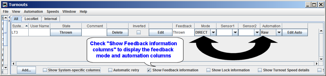
(Click the image for a larger version of the image.)
The effect of this setting is to (potentially) reduce the maximum rate at which the command station must forward LocoNet turnout control messages to the DCC track signal. This (potentially) reduces the demands on the command station's buffering, thus potentially reducing the likelihood of the command station's buffer filling.
When this mode is used for a given turnout, JMRI does not make any use of the "Bypass Bushby Bit" or the "Send ON and OFF" configuration information.
This type of JMRI configuration does not affect those LocoNet turnout control messages generated by other LocoNet devices.
There is some question about how Digitrax command stations handle the messages associated with this mechanism, which must be buffered by the command station, and whether that command station buffering is any different than the buffering used with "normal" and "alternate" LocoNet turnout messages.
Using this JMRI feature reduces the number of LocoNet switch control messages which need to be forwarded to the DCC track signal, which reduces the probability that any given LocoNet switch command will arrive at the command station when its buffer is already full.
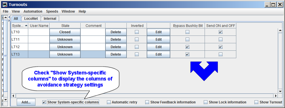
To configure this JMRI operating mode, it is necessary to configure each individual JMRI turnout, via the JMRI "Turnout Table". The image below shows that turnouts LT10 and LT12 are configured to send both "ON" and "OFF" messages - each of these turnouts have the "Send ON and OFF" checkbox checked. In the image, turnouts LT11 and LT13 have the checkbox unchecked, so JMRI will only send "ON" messages when JMRI controls these turnouts.
 .
.
(Click the image for a larger version of the image.)
If the "Send ON and OFF" column is not visible, you may check the "Show System-specific columns" checkbox at the bottom of the window, or you may "right-click" while pointing to any visible header and then check the "Send ON and OFF" checkbox.
When a new JMRI turnout is created, the "Send ON and OFF" checkbox is checked by default.
Note that the "Send ON and OFF" checkbox settings have no effect LocoNet switch control messages sent by other LocoNet agents.
When the command station "Bushby" feature is enabled, only turnout commands using a special LocoNet message type will be forwarded to the DCC track signal. This can be used in a few different ways.
This option is only suitable for layouts where there are no devices which are controlled solely by the DCC track signal (or its low-power equivalent on the LocoNet cable.
Note that some devices get their control messages from the low-power DCC track signal on the LocoNet RailSync wires or from the LocoNet Data wires. If this type of device must be controllable when the command station's Bushby feature is enabled, the device must be configured to get control messages from the LocoNet Data wires. An example is the SE8C, which defaults to receive control messages from the low-power DCC track signal on the LocoNet cable. To configure the SE8C to be controlled by LocoNet messages, set the SE8C OpSw14 to "C"losed. Other device types may require similar re-configuration to be controllable.
To configure this JMRI feature for a turnout, define the turnout (if necessary) in the JMRI "Turnout Table", and place a check in the turnout's "Bypass Bushby Bit" checkbox. If the "Bypass Bushby Bit" column is not visible in the table, you may right-click on the table column header row and check "Bypass Bushby Bit", or check the "Show system-specific settings" checkbox at the bottom of the window.
In the image above, turnouts LT12 and LT13 show the "Bypass Bushby Bit" checked. When JMRI attempts to control either of these two turnouts, JMRI will send an alternate LocoNet turnout control message ("OPC_SW_ACK"), which will bypass the command station's "Bushby" blocking of "regular" LocoNet turnout control messages ("OPC_SW_REQ").
Note that the command station still buffers the "alternate" LocoNet turnout control messages, and turnout message rejection can occur. As such, it is important to configure the "Bypass Bushby Bit" option only on those turnouts which require conrol via the DCC track signal or the low-power version that is available on the LocoNet cable's RailSync wires.
Also note that setting the JMRI "Bushby Bit Bypass" feature a given turnout does not affect how turnout control messages from other LocoNet are encoded. Unless another LocoNet device uses the "alternate" LocoNet turnout control message, that LocoNet device will not be able to pass turnout control messages to the DCC track signal when the command station "Bushby" feature is enabled.
See the JMRI Standalone LocoNet® page for background, ideas, and suggestions for implementing a Standalone LocoNet.
Some more recent Digitrax command stations will refuse to accept switch commands when track power is turned off. This can result in a "storm" of repeated switch messages on LocoNet if track power is off when switch messages are sent. This problem can be avoided by ensuring that track power is on when switch messages are to be sent.
When JMRI has multiple active connections to a single LocoNet, it may be necessary to
configure all but one of the active LocoNet connections for "Turnout Command Handling"
type of "Only One", with one active LocoNet connection configured for one of the other
"Turnout Command Handling" types. Failure to do this could cause the various JMRI LocoNet
connection instances to independently attempt to resolve any turnout messages which have
been rejected by the command station. This could result in a storm of turnout command
retries on LocoNet.
Similarly, when multiple JMRI instances are working with the same LocoNet, only one JMRI
connection to the LocoNet should be configured for a "Turnout Command Handling" type
other than "Only One". Failure to do this could cause the various JMRI LocoNet connection
instances to independently attempt to resolve any turnout messages which have been
rejected by the command station. This could result in a storm of turnout command retries
on LocoNet.
JMRI supports a wide variety of LocoNet hardware and features. JMRI provides a wide variety of hardware-specific tools to assist in configuring the devices. And JMRI provides a number of tools to monitor the operation of LocoNet. Most of these features are described in the JMRI "Help" pages linked below (also refer to the sidebar).
Some LocoNet devices can be configured via JMRI a "roster" entry. Simply select the appropriate "decoder" name when creating a new roster entry. These include:
Often, these "decoder" definitions have some limitations on which features can be configured, and, where appropriate, limitations on the supported range of "board id" values. These limitations are documented on a "Notes" tab within the "comprehensive" programmer window.
Note that JMRI generally provides other (historical) tools which are able to configure the same set of features via tools in the "LocoNet" menu. Any changes made to device configuration using the historical tools will not be reflected in a roster entry for the device. If you wish to keep the roster updated with any changes made via historical tools or using other tools or processes, it will be necessary to manually update the roster entry.
Some Digitrax devices can be configured for "Board ID" number (sometimes called Board Address). This value is typically used to influence which Turnout, Sensor, Reporter, and/or Power Manager section numbers are used by the device.
Digitrax devices which make use of "Board ID" numbers, but which cannot be programatically configured, include:
For these devices, JMRI cannot configure the Board ID number under JMRI's control without user intervention. It is, however, possible to configure the Board ID number using JMRI and manual intervention. The process is to follow the directions found in the device manual for changing Board Address (Board ID), but use JMRI's "Turnout Control" tool instead of a LocoNet throttle.
Below is a table showing, on the left, the Digitrax instructions copied from the BDL168 manual, and, on the right, the instructions when using JMRI. Similar instructions may be used to configure other the Board Address (Board ID) on other Digitrax devices.
| Step/th> | Digitrax Instructions for changing BDL168 Board Address | Instructions for changing Board Address (Board ID) when using JMRI |
|---|---|---|
| 0 | (A step not included in Digitrax documentation, but one
that is necessary regardless of what method you use!) 0. Ensure that NO OTHER ACTIVITY is occurring on LocoNet! If anything causes generation of a LocoNet Turnout Control message after the device button has been pressed, but before you issue the turnout control message to the specific number you desire, then the board will be configured to use that unexpected turnout number, leaving the board unmanageable at the Board ID number you are expecting! Be aware that movement of trains on layouts where signaling is implemented can cause generation of LocoNet Turnout control messages! |
|
| 0.25 | Configure JMRI to communicate with with your LocoNet hardware. | |
| 0.5 | See Note 1 below before proceeding. This step applies both for the Digitrax procedure and the JMRI-based procedure. | |
| 1 | Note: Steps 1 thru 4 of the Digitrax instructions are from Section "8.1 To set up the BDL168 board address" of the Digitrax BDL168 manual, with some comments added by JMRI developers.) | Power up your layout, BDL168, and start JMRI. |
| Power up your BDL168. | ||
| 2 | Press the switch behind the green ID LED for about 1 second, then release it. The
green ID LED will blink. The red option LED will not light. This let's you know that you
are in board address set up mode. (Note: These instructions apply to BDL16, BDL162, and BDL168 devices. Other instructions, buttons, and LED color/flashing conditions may apply for other device types. See the appropriate manual for device-specific instructions!) |
Same as per Digitrax instructions. |
| 3 | Connect a DT or UT series Digitrax throttle to the BDL168's LocoNet connector. (This can only be done with a Digitrax LocoNet throttle or equivalent software). | Open JMRI's "Turnout Control" tool, via "Tools->Turnout Control" |
| 4 | Go into SWITCH mode on the throttle. Select the switch number that corresponds to the board address you want to set and issue a closed "c" command to set the board address. The board address is changed as soon as you issue the SWITCH command. See following instructions for using specific Digitrax throttles for setting the address. (Those instructions omitted here.) | Enter the switch number which corresponds to the board address you want to set in the number entry box below "Turnout" at the top of the JMRI "Turnout Control" tool. As an example, to set Board Address (Board ID) to 4, enter "4" (without quotes". Then activate the window's "Closed" button. |
| 5 |
(A JMRI-specific step, not included in Digitrax documentation, which applies regardless
of which method you use.) See Note 2 below for important information on JMRI behaviors which may influence how JMRI sees the device and which may require changes to any pre-existing JMRI uses of affected Turnout, Sensor, and/or Reporter configurations, and/or customized scripts monitoring for LocoNet Power Management messages. |
|
| 6 | Quit and Restart JMRI. See Note 3 below, for more information on why this can be important. | |
| Note 1 |
Some devices, by default, get their turnout control messages from the DCC track signal,
and rely upon the command station to forward the LocoNet turnout control messages as
DCC track signal stationary decoder packets.
|
|
| Note 2 | The Board ID number typically implies the Turnout, Sensor, Reporter, and/or power management "addresses" used by the device. Changing the Board ID number typically forces the device to use different addresses. This can mean a disruption to the JMRI functionality which worked before the Board ID number was changed. If you have used "User Names" to reference those items, it is usually sufficient to give a similar User Name to each "relocated" Turnout, Sensor, or Reporter object, and then change each reference to the old object User Name to reflect the new User Name. | |
| Note 3 | If JMRI has "pre-populated" the Turnouts or Sensors table with information about the device, it will be necessary to quit and restart JMRI so that any information that was "pre-populated" from the device based on its old Board ID value will _not_ be remembered. Restarting JMRI causes JMRI to request the "pre-population" information, and if the device responds to the request, the device should respond with its information and the Turnouts and/or Sensors table should be pre-populated. | |
After completing the instructions as noted above, the device should be configured for the selected Device address.
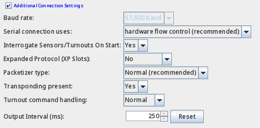
At this time, Digitrax "expanded" slots are not directly supported. This has several implicaitons:
As such, many users find that disabling DCS240 "expanded" slot capability can improve some aspects of JMRI "throttle" functionality, including WiThrottle Server funcitonality.
Additional discussion may be found here.
At this time, the Digitrax BXP88 and BXPA1 devices do not support a mechanism to allow JMRI to program individual device OpSw settings via LocoNet messaging.
While JMRI cannot provide mechanisms to configure these devices, for their block detection and transponding features, their behavior is similar to the BDL16x device. JMRI's existing support for BDL16x block detection and transponding features provides appropriate support for the BXP88/BXPA1 detection and transponding operational features. JMRI's existing support for PM4x power management features provides appropriate support for the BXP88/BXPA1 power management operational features.
The LNWI similarly does not provide mechanisms to allow JMRI configuration of individual LNWI OpSw settings. However, some LNWI "SSID" information may be influenced by the operations performed by the Configure Duplex Group tool. Note that some specific LNWI OpSw settings are able to block the effect of that tool upon the LNWI's SSID configuration.
LocoNet® is a registered trademark of Digitrax, Inc.