LocoNet® systems provide "general purpose inputs" via LocoNet "Sensors", provide "general purpose outputs" via either LocoNet-connected or DCC-connected "Turnouts", and provide "Reporter zone" numbers via LocoNet "Transponding zones". Each of these object types use independent addressing within LocoNet messaging.
There is a direct relationship between an object's LocoNet address and one of two ways in which JMRI works with the object. The object's JMRI "System Name" has this direct relationship.
Alternately, JMRI allows the user to reference the object using a "User Name", which is a user-defined name for the object. When referencing these objects within JMRI, one can generally use either the object's "User Name" or its "System Name" to reference the object.
Use of these descriptive "User Names" to reference objects within JMRI can simplify development and debugging of JMRI "Signaling" configurations and "Logix Conditionals". JMRI developers suggest that users make use of object "User Names" wherever possible. Additional general information on JMRI "System Names" and "User Names" may be found here.
JMRI communicates with the individual physical turnouts, sensors, reporters and other physical objects via individual "system names". Each physical object which JMRI interacts with has a unique "system name". A typical JMRI system name is made up of a letter which indicates the connection type, plus another letter which indicates the type of object, plus one or more digits to indicate which specific object is being referenced.
LocoNet system names typically look like "LT5", "LS2013", and "LR535". These three system names represent LocoNet Turnout 5, LocoNet Sensor 2013, and LocoNet Reporter 535, respectively.
It is important to note that JMRI generally treats each unique object "system name" as a separate object. This means that the sensor with system name "LS9" is a separate entity from the objects referred to by the system names "LT9", "LR9", and "L2S9". It is possible that specific LocoNet hardware imposes some specific relationship between various objects with the same address, but JMRI does not assume any relationship between them.
Similarly, where a JMRI installation has more than one simultaneously-active LocoNet connection, JMRI will be configured with differing "prefix" information for each connection. The unique prefixes are used in the JMRI system names to indicate which LocoNet connection the object refers to. "LT5" refers to switch 5 on a system connection with prefix "L", while "L2T5" refers to switch 5 on a different system which has a prefix of "L2". Those two independent system names denote two independently-controlled and independently- controllable turnouts on the two independent communication channels.
For user monitoring of these objects, and, as appropriate, user control of these objects, JMRI provides a "table" for each of these object types. These tables list all of the objects of a given type (i.e. "Turnouts") which are known to JMRI at a given time. Each Table shows the System Name, User Name (if assigned) and State of each known object. Additional configuration and comment information may also apply for some object types; where applicable, additional configuration buttons and information fields may appear in the Table on the same line as a given object.
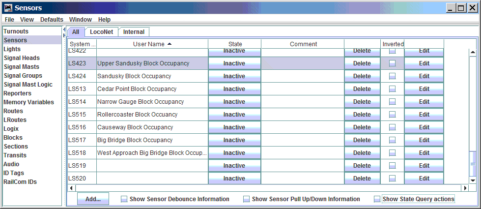
LocoNet "Turnouts" are found in the "Turnout Table", LocoNet "Sensors" are found in the "Sensor Table", and LocoNet "Transponding Zones" are found in the "Reporters Table". Entries to these tables may be made manually by the user, or automatically when JMRI "sees" a LocoNet message which implies an object which is not already in the appropriate table. A sample of a JMRI Sensor Table is shown below.
See Loading and Storing Your Work.
From the Tables window, with the "object type" selected in the list at the left ("Turnouts", for example), select the "Add..." button which is found near the bottom of the window. This opens a new window where you may enter the information for the new object. If you are asked for a "Hardware Address", you should not specify a "System Name"; instead you should enter the "address" of the item you are adding - for example, "14" (without the quotes), to specify an object with hardware address "14". The tool will figure out the full "System Name" from the "System Connection" setting and the "Hardware Address" value.
As an example of manually adding a LocoNet turnout, consider adding turnout number 34, and assigning the object the "User Name" "Yard throat 3/4 track switch". This may be done via the "Turnout Table" by pressing the "Add..." button at the bottom of the table, then entering the information shown here.
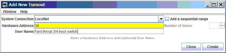
Activate the "Create" button to add the new entry into the "Turnout Table".
When multiple "connections" are configured in the current JMRI Configuration Profile, the "System Connection" box allows selecting between the connections which are available. JMRI will create a system name using a connection prefix which applies to the selected "system connection".
Because an object's System Name must be unique, the tool will report an error message if you enter information which would duplicate a pre-existing object's System Name.
Digitrax throttles and JMRI use identical numbering for LocoNet turnouts. The "Hardware Address" number JMRI uses to refer to a turnout is exactly the same number as used when using a Digitrax throttle to control a "Switch". Digitrax documentation describes LocoNet turnout numbers as having a range from 1 to 2048. JMRI uses a "System Name" to refer to the hardware object, and the "System Connetion Prefix" and "object type character" must be used in conjunction with the "Hardware Address" number to make a complete System Name for a LocoNet Turnout.
For example, if a JMRI is configured for a single LocoNet connection, and that connection has the default "System Prefix" of "L", and a turnout on that LocoNet connection has an address of 12, then the associated JMRI System Name would be "LT12", where "L" is the "system connection prefix", "T" represents a "Turnout" object type, and "12" is the "Hardware Address" of the turnout.
As another example, if a JMRI LocoNet connection has a user-defined system connection prefix of "GRAPE", and a turnout on that connection has an address of 12, then the associated JMRI System Name would be "GRAPET12", where "GRAPE" is the "system connection prefix", "T" represents a "Turnout" object type, and 12 is the "Hardware Address" of the turnout. Note that if JMRI is configured for two connections, one with system connection prefix "L" and the other with system connection prefix "GRAPE", the JMRI system name "LT12" refers to a turnout object which is considered entirely separate from the turnout referred to by the object with system name "GRAPET12".
The JMRI Turnout Table shows a list of all Turnouts JMRI is aware of. Every time JMRI sees a LocoNet message which specifies a Turnout, JMRI updates the "known state" of an existing entry in the Turnout Table or JMRI creates a new entry if one does not already exist. When JMRI automatically adds a Turnout Table entry in this way, it does so with a blank "User Name". Users may update the "User Names" in the Turnout Table. As noted above, it is helpful to save your Turnout Table changes so that you may re-load those updates into JMRI at a future time.
The Turnout Table provides a useful snapshot of the current state of all Turnouts "known to JMRI", and allows the user to change the state of those Turnouts.
Additional information on Turnouts and the Turnout Table may be found at the main JMRI Turnouts page.
JMRI provides an object-type called "Lights". For some DCC systems, "Light" objects are defined and addressed separately from "Turnout" objects. LocoNet does not define a separate "Light" object. To support "light" objects on LocoNet connections, JMRI maps its "Light" objects into equivalent LocoNet "Turnout" objects.
This means that changing the state of a JMRI "Light" object with System Name "LL123" will actually modify the LocoNet turnout which corresponds to the JMRI turnout with System Name "LT123".
Additional information on Lights and the Light Table may be found at the main JMRI Lights page.
Digitrax throttles and JMRI use identical numbering for LocoNet sensors. The "Hardware Address" number JMRI uses to refer to a sensor is exactly the same number as is reported by some Digitrax throttles which can monitor for and display information from LocoNet sensor state messages. Digitrax documentation describes LocoNet sensor numbers as having a range from 1 to 4096. JMRI uses a "System Name" to refer to the hardware object, and the "System Connection Prefix" and "object type character" must be used in conjunction with the "Hardware Address" number to make a complete System Name for a LocoNet Sensor.
For example, if a JMRI is configured for a single LocoNet connection, and that connection has the default "System Prefix" of "L", and a sensor on that LocoNet connection has an address of 12, then the associated JMRI System Name would be "LS12", where "L" is the "system connection prefix", "S" represents a "Sensor" object type, and "12" is the "Hardware Address" of the Sensor.
As another example, if a JMRI LocoNet connection has a user-defined system connection prefix of "GRAPE", and a sensor on that connection has an address of 12, then the associated JMRI System Name would be "GRAPES12", where "GRAPE" is the "system connection prefix", "S" represents a "Sensor" object type, and "12" is the "Hardware Address" of the sensor. Note that if JMRI is configured for two connections, one with system connection prefix "L" and the other with system connection prefix "GRAPE", the JMRI system name "LT12" refers to a sensor object which is considered entirely separate from the turnout referred to by the object with system name "GRAPES12".
The simplest way to find the correct number for a given Sensor is to open a JMRI "LocoNet monitor" window, and watch the window while causing a change to be reported by the sensor. Look for an entry which shows a changing state which matches the activity. For sensor which is used to detect block occupancy, remove all detectable equipment, then place a locomotive onto the chunk of track which is monitored by the block occupancy detector. Watch the messages in the monitor for a sensor message. Then remove the equipment from the block to see the sensor change state again. Confirm that the sensor number is consistent.
The message shown in the LocoNet Monitor window will typically look something like this:
Sensor LS514 is High
This message is interpreted to mean that The sensor with "System Name" of "LS514" and an undefined (empty) "user name" is currently "High". In this particular case, the sensor is being used to report block occupancy detection, and "High" means that the block is "occupied".
The JMRI Sensor Table shows a list of all Sensors of which JMRI is aware. Every time JMRI sees a LocoNet message which specifies a Sensor, JMRI updates an existing entry in the Sensor table or creates a new Sensor entry if one does not already exist. Each Sensor in the table can be assigned a "User Name". As noted above, it is helpful to save your Sensor Table changes so that you may re-load those updates into JMRI at a future time.
The Sensor Table also provides a useful snapshot of the current state of all known Sensors.
Additional information on Sensors and the Sensor Table may be found at the main JMRI Sensors page.
Digitrax Transponding is handled via the Reporter mechanism in JMRI. Reporters gather information from the layout and make it available when it changes. JMRI typically refers to LocoNet Reporters using the System Name LRx where L is the system connection prefix for a LocoNet connection and x is a number which corresponds to a detection zone. The system connection prefix may be different when multiple System Connections are configured.
Within JMRI, Transponding Zones are numbered sequentially from 1 to 4096. This differs from the way Digitrax throttles report Transponding zones. If the "Find" feature is activated on a DT300x, DT40xx, or DT500x throtte, the display will report zones between 0 and 4095. When comparing JMRI transponding zone numbers and Digitrax throttle-reported zone numbers, the JMRI transponding zone number is always one higher than the number reported by the Digitrax throttle.
Current BDL16x hardware implements only odd-numbered Transponding zones. The first Transponding zone of a BDL16x board is reported as JMRI Reporter number (1 +(board address -1) * 16). The second Transponding zone of a BDL16x board is reported as Reporter number (1 +(board address -1) * 16) + 2.
Reporter numbering is summarized in the table below:
| BDL16x Board Address | Zone | Reporter Number |
| 1 | A | LR1 |
| B | LR3 | |
| C | LR5 | |
| D | LR7 | |
| E | LR9 | |
| F | LR11 | |
| G | LR13 | |
| H | LR15 | |
| 2 | A | LR17 |
| B | LR19 | |
| C | LR21 | |
| D | LR23 | |
| E | LR25 | |
| F | LR27 | |
| G | LR29 | |
| H | LR31 | |
| 3 | A | LR33 |
| B | LR35 | |
| C | LR37 | |
| D | LR39 | |
| E | LR41 | |
| F | LR43 | |
| G | LR45 | |
| H | LR47 | |
| ... | ||
| 256 | A | LR4081 |
| B | LR4083 | |
| ... | ||
| H | LR4095 | |
BXP88 devices implement sequential Transponding zone numbers. The first Transponding zone of a BXP88 is reported as JMRI reporter number (8 * (board address -1)) + 1, and the last Transponding zone of a BXP88 is reported as JMRI reporter number (8 * (board address -1)) + 8. This numbering happens to match the BXP88 block occupancy Sensor numbering. If a BXP88 detection section reports its block occupancy via JMRI's LS45, then the transponding zone for that section will be via JMRI's LR45.
BXP88 Reporter numbering is summarized in the table below:
| BXP88 Board ID | Detection Section | Reporter Number | Detection Sensor |
| 1 | 1 | LR1 | LS1 |
| 2 | LR2 | LS2 | |
| 3 | LR3 | LS3 | |
| ... | |||
| 8 | LR8 | LS8 | |
| 2 | 1 | LR9 | LS9 |
| 2 | LR10 | LS10 | |
| 3 | LR11 | LS11 | |
| ... | |||
| 8 | LR16 | LS16 | |
| 3 | 1 | LR17 | LS17 |
| 2 | LR18 | LS18 | |
| 3 | LR19 | LS19 | |
| ... | |||
| 8 | LR24 | LS24 | |
| ... | |||
| 256 | 1 | LR2040 | LS2040 |
| 2 | LR2041 | LS2041 | |
| 3 | LR2042 | LS2042 | |
| ... | |||
| 8 | LR2048 | LS2048 | |
BXPA1 devices implement a single Transponding zone. That zone is numbered as being equal to its Board ID value. For a BXPA1 with Board ID set to N, JMRI will typically report via reporter "LRN". Note that BXPA1 block occupancy is reported via a different number than the BXPA1 transponding zone.
BXPA1 Reporter numbering is summarized in the table below:
| BXPA1 Board ID | Detection Section | Reporter Number | Detection Sensor |
| 1 | 1 | LR1 | LS1 |
| 2 | 1 | LR2 | LS3 |
| 3 | 1 | LR3 | LS5 |
| 4 | 1 | LR4 | LS7 |
| 5 | 1 | LR5 | LS9 |
| ... | |||
| 1024 | 1 | LR1024 | LS2047 |
The JMRI Reporter Table shows a list of all Reporters JMRI is aware of. JMRI creates an entry in this table for each new Transponding zone for which it sees a Transponding message. Each Reporter in the table can be assigned a "User Name". You may manually enter Reporter Table entries when you know the correct System Name for the reporter; it will be updated whenever a LocoNet message for that reporter is seen.
Once you have the Transponding hardware installed and at least one Locomotive transponding properly, it is simple to fill in the Reporter Table for each Transponding zone by running a transponding-enabled locomotive through all transponding-capable zones. It may be convenient to fill in a "User Name" in the JMRI Reporter Table at the time when the Locomotive first enters each Transponding zone. As noted above, it is helpful to save your Reporters Table changes so that you may re-load those updates into JMRI at a future time.
Additional information on Reporters and the Reporter Table may be found at the main JMRI Reporter page.
JMRI's LocoNet implementation makes use of a variety of other LocoNet-specific addressing schemes for programming LocoNet-based devices.
Some LocoNet-based devices may be configured with a "Board ID" number which allows computer-based device programming and often influences which LocoNet addressing a device uses. Not all LocoNet devices have "Board ID" numbers.
For example, a Digitrax DS64, connected on the LocoNet connection "L", and set for the "Board ID" 2 will default its outputs to be controlled by LocoNet turnouts at addresses 5 thru 8. Within JMRI, the turnouts would be controlled by System Names LT5, LT6, LT7, and LT8. When properly configured, the DS64's inputs will default to act as LocoNet "General Sensor" values at sensor addresses 9 thru 16 (and JMRI LS9 thru LS17), or as LocoNet "Turnout Feedback" values for turnout addresses 5 thru 8.
JMRI requires use of Board ID value when configuring "Op Switch" values in BDL16x, DS64, PM4x, and SE8C devices. This allows the JMRI device programming mechanisms to program only a single device, selected based on the device's Board ID value.
NOTE - Board ID values have independent addressing ranges for each device type. Board ID values for DS64 devices are independent from Board ID values for BDL16x devices, Board ID values for PM4x devices, and Board ID values for SE8C devices. You may have one LocoNet which uses Board ID 2 for a PM42 device and a BDL16x device and a DS64 device and a SE8C device. In this case, JMRI's device configuration tools will be able to configure the devices independently. But the sensor, turnout, reporter, etc. objects of the devices may overlap each other. Be careful to choose Board ID values for each device such that no two devices implement addressed objects which overlap addressed objects of the same type but implemented on another LocoNet device.
(The following was first fully available in JMRI 4.1.2. Versions before that may not be complete).
Like decoders store Configuration Variables (CVs) to hold their settings, some LocoNet-compatible (non-Digitrax) devices implement System Variables (SVs).
It is believed that Digitrax hardware does not make use of SVs, so users who only have LocoNet hardware produced by Digitrax may skip this section.
There are (at least) two variations of the protocol for accessing these. JMRI can use version 1 or version 2 to access compatible SVs by selecting "System Variable Type 1" or "System Variable Type 2" as the programming mode, respectively. This option is presented when you're using a LocoNet System Connection that actually connects to a LocoNet, such as a LocoBuffer-USB or PR3 in MS100 mode.
SVs are numbered from 1 to 127 for version 1 hardware and from 1 to 65,535 for version 2 hardware. Their names can be written in several formats:
| CV Number |
Prior Content |
Value Written |
Masked Value |
New Content |
|---|---|---|---|---|
| CV1^01 | 0x55 | 0x22 | 0x01 | 0x23 |
| CV1^01 | 0x54 | 0x22 | 0x01 | 0x22 |
| CV1^0F | 0x55 | 0x33 | 0x03 | 0x53 |
| CV1^F0 | 0x55 | 0x33 | 0x03 | 0x53 |
| CV1^33 | 0xF0 | 0x77 | 0x30 | 0x37 |
| Old Style | JMRI Number |
|---|---|
| 10/1 | 10 |
| 83/1 | 83 |
| 83/2 | 339 |
| 83/0 | -173 |
You can use all of the DecoderPro tools to manage a board using the LocoNet SV protocol if you provide an appropriate definition file. These are in the same format as a decoder definition file, except that to specify the LocoNet SV Version 2 protocol you modify the "programming" element to looks like:
    <programming direct="no" paged="no" register="no" ops="no">
        <mode>LOCONETSV2MODE</mode>
    </programming>
LocoNet SV Version 1 protocol is the same, except you specify LOCONETSV1MODE.
Note that the version 1 protocol is no longer recommended. If you're writing a decoder definition for a board that can use both, you should skip version 1 by providing just the LOCONETSV2MODE option.
(The following was first fully available in JMRI 4.9.7. Versions before that may not be complete).
Digitrax PM4, BDL168, SE8c and DS64 boards use a special messaging protocol to program their Op Switches. JMRI supports this mode in Roster-based programming, so you can treat these types of boards in much the same way as you treat mobile decoders in your locomotives - you may program them using the JMRI "Symbolic" programmers (i.e. the Roster).
Within the JMRI "Symbolic" programmer, the "decoder address" specifies the Board ID number assigned to the device being programmed. Since the programmer uses the Board ID number, it is not necessary to re-wire your LocoNet when programming these devices. The individual "Op Switches" are referenced using a designator which specifies a "device type number" and the OpSw number, with the two numbers separated by a ".". For example, a CV numbered as "113.7" is a reference to a BDL16x device (i.e. 113), OpSw 7. You may ignore the "device type number" when referencing CV numbers shown in the JMRI "Symbolic Programmer".
(The following was first fully available in JMRI 4.9.7. Versions before that may not be complete).
Digitrax command stations use a special messaging protocol to program their Op Switches. JMRI supports this mode in Roster-based programming, so you can treat these command stations in much the same way as you treat mobile decoders in your locomotives - you may program them using the JMRI "Symbolic" programmers (i.e. the Roster).
Within the JMRI "Symbolic" programmer, the "decoder address" is ignored, since there can only no more than one command station on a given LocoNet at a given time. The individual "Op Switches" are referenced using a designator which specifies a "command station OpSw" access type and an Op Switch number, with the two parts of the designator separated by a ".". For example, a CV numbered as "csOpSw.007" is a reference to a "command station OpSw" numbered "7".
LocoNet® is a registered trademark of Digitrax, Inc.